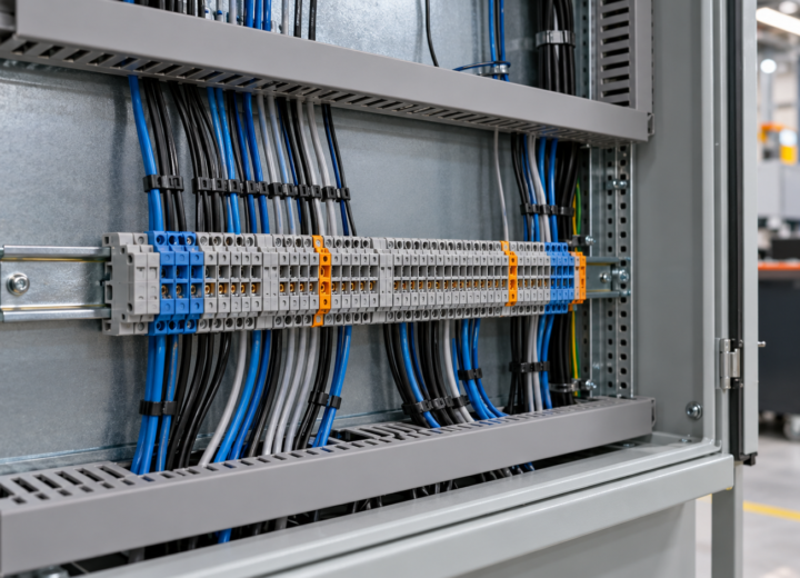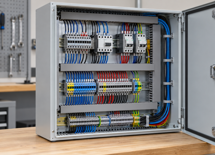
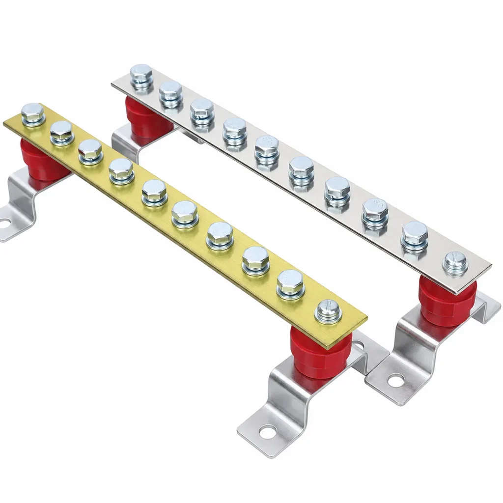
When a cabinet assembler in Rotterdam encountered a clearance problem while reviewing wiring drawings for a low-voltage enclosure, the issue looked minor on paper. During fit-up, however, the planned terminal alignment brought a conductor too close to an adjacent connection point. The visible failure was not a faulty copper part: it traced back to an incomplete assembly reference, where mounting orientation, conductor approach, and clearance had not been specified together. That hypothetical case is why terminal selection must begin with the cabinet interface, not the part name alone.
Summary: A Copper Busbar Wiring Terminal, a Copper Busbar Assembly, and an Electrical Cabinet Copper Busbar describe related but different levels of a connection system. IEC 61439-1 addresses general rules and verification for low-voltage switchgear and controlgear assemblies; it does not certify a loose terminal by itself. Start with a drawing review that records conductor size, hole pattern, orientation, insulation, and required clearances, then have the complete assembly verified for its intended duty.
A Copper Busbar Wiring Terminal should be defined by its interfaces
Copper conductors are common in cabinet power paths because a formed bar can make a short, repeatable connection between devices, distribution points, and external conductors. The Copper Development Association’s busbar guidance is useful background for material and layout decisions, but final dimensions and temperature-rise performance require verified engineering in the actual enclosure. A terminal is therefore a mechanical and electrical interface, not simply a piece of copper with a drilled hole.
Specify both ends of the interface before comparing shapes. On the device side, record stud or pad geometry, fastening method, accessible tool direction, and the surface that will carry contact pressure. On the conductor side, record the cable lug, formed strap, or adjacent bar that will mate with it. A nominal hole diameter alone cannot show whether the hardware stack, washer arrangement, or installation tool will fit.
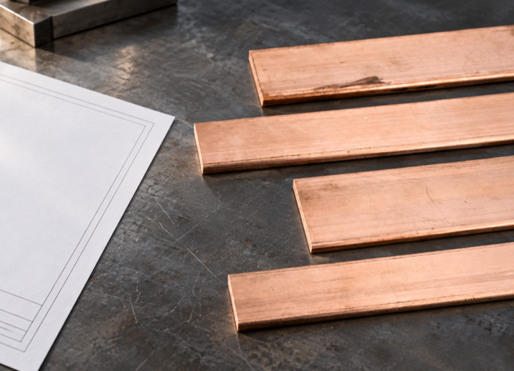
The essential drawing fields are material designation, finished or uncoated condition where relevant, thickness, width, bend locations, hole size and centres, edge distances, and datum references. Also identify left- or right-hand orientation when a mirrored part could be installed incorrectly. For a Copper Busbar Wiring Terminal, these fields connect procurement language to the dimensional checks used during fit-up.
A drilled mounting hole determines where hardware passes through; it does not by itself define the effective contact area or the current path. The mating pad, overlap, flatness, coating condition, and hardware sequence affect the joint. Copper busbar design references explain why geometry and heat dissipation matter, while the completed cabinet must still be assessed under its actual loading, enclosure, and ambient conditions.
Torque is another controlled input, but it should come from the applicable fastener, device, lug, or assembly instruction rather than a generic terminal rule. Documenting the specified tightening process, tool access, and inspection point helps prevent variation between assemblers. Where a design is altered, repeat the relevant engineering review instead of treating a previous torque value as transferable.
A Copper Busbar Assembly must be compared as a system, not a commodity part
Two parts with similar copper content can create different assembly effort. A flat connection may permit a direct approach with a standard tool, whereas a bent terminal can improve routing but introduce a tolerance stack at a cabinet wall or device pad. The right comparison includes drawing completeness, installation accessibility, inspection steps, replacement risk, and the consequence of discovering a mismatch after other hardware is installed.
The table below is a value comparison, not a rating of every available design. It distinguishes the questions that should be resolved for a simple flat connection and for a formed or multi-interface connection. Any thermal, short-circuit, dielectric, or mechanical verification method should be selected by the engineer responsible for the finished assembly and its declared duty.
| Comparison dimension | Simple flat connection | Formed or multi-interface connection |
|---|---|---|
| Drawing control | Hole pattern and contact faces are central. | Hole pattern, bends, datums, and handedness are central. |
| Installation access | Often check direct tool approach and washer stack. | Check tool approach, bend clearance, and assembly sequence. |
| Maintenance planning | Confirm inspection access to the joint. | Confirm removal path without disturbing adjacent conductors. |
| Total-cost driver | Mismatch can cause rework at the connection point. | Late-fit mismatch can affect several mounted components. |
An illustrative total-cost calculation should include more than the supplied part. If one unclear datum requires a drawing revision, a replacement shipment, a new fit-up, and repeated inspection, its cost may exceed the difference between two initial quotations. This is not a claim about any project outcome; it is a procurement reminder to value complete information and first-fit compatibility alongside unit-cost tendency.
Where a drawing calls for several linked conductive components, review the Copper Busbar Assembly as one dimensional chain. The device pad, hardware, terminal form, cable-lug approach, enclosure panel, and protective barriers all affect whether the intended connection can be assembled and later inspected safely.
An Electrical Cabinet Copper Busbar selection changes with its application
Application context converts a general terminal description into a usable specification. A compact distribution cabinet may prioritize service access and segregation; a renewable-energy enclosure may impose different routing, environmental, and device-interface constraints. The following table organizes questions by use case. It is a selection aid, not a substitute for the applicable assembly verification or jurisdiction-specific requirements.
| Application or selection dimension | Questions to settle on the drawing | Evidence to retain |
|---|---|---|
| Panel-building distribution | Can the terminal, neutral bar, and protective barriers be installed and reached in sequence? | GA drawing, hole schedule, hardware stack, inspection instruction. |
| Renewable-energy equipment | What are the device pads, cable exits, enclosure conditions, and isolation arrangement? | Interface drawing and assembly duty assumptions. |
| OEM replacement or revision | Which dimensions, bends, and mating faces must remain interchangeable? | Controlled revision, sample fit-up, and change record. |
| Distribution sourcing | What drawings, quantities, packaging, and traceable revision details are needed? | Approved drawing and order reference. |
The phrase Electrical Cabinet Copper Busbar is useful for discovery, but it should not be the complete purchase description. A buyer still needs the interface details that distinguish one cabinet location from another. For example, a connection beside a neutral-bar arrangement may need particular clearance, access, and segregation checks even when its conductive material is similar to a nearby phase connection.
Early assembly review is especially helpful for cabinet and energy-equipment teams working across several interfaces. Relevant cabinet and energy applications can be used to frame the operating context, but the final design basis should remain the controlled drawing and the verification plan for the completed equipment.
Standards define the assembly context and the limits of compliance claims
IEC 61439-1 sets general rules for low-voltage switchgear and controlgear assemblies and addresses verification at the assembly level. It can inform the specification of an Copper Busbar Assembly, yet it should not be represented as a certificate for an individual loose terminal. The responsible party must determine which verification requirements apply to the finished assembly, its design, and its declared characteristics.
In the United States, OSHA 29 CFR 1910.303 provides general requirements for electrical equipment. Its applicability depends on jurisdiction and the workplace context; it is not a universal product label. NEMA industrial-control standards likewise depend on the particular product and application. Calling either source a blanket certification can create an unsupported commercial claim and confusion during customer review.
IEEE 3001.2 is an IEEE recommended practice related to evaluating electrical service requirements. It does not define terminal torque. The distinction matters because a credible submittal separates system-level design guidance, assembly verification, manufacturer installation instructions, and any test evidence actually available for the supplied configuration.
A sensible compliance record names the destination market, intended use, governing assembly standard, drawing revision, and any required verification responsibility. Where a buyer asks for a specific test, request the method, acceptance criteria, specimen definition, and reporting expectation. That approach prevents an informal material statement from being mistaken for proof of performance under a different enclosure or installation condition.
A disciplined selection guide reduces uncertainty before a cabinet is built
First, issue a controlled interface drawing rather than an isolated product sketch. Mark device pads, fastener sizes, conductor approach, hole centres, bend directions, and minimum physical clearances. Second, carry out a practical fit-up review that includes the installer’s tool path and the order in which neighbouring parts will be mounted. These actions expose conflicts while changes are still comparatively contained.
Third, establish the performance basis for the finished cabinet: operating current assumptions, enclosure conditions, protection concept, and required verification route. Fourth, agree the acceptance package—approved drawing, revision identifier, material or finish requirements where specified, and inspection documentation. These steps do not replace engineering; they make the engineering decision visible to purchasing and production.
For standard parts or drawing-based conductive work, DONGYAO can support the sourcing conversation with the relevant drawing and interface information. A drawing-review service is most useful when it tests the purchase request against mounting, routing, and assembly references before production. That is a more reliable starting point than assuming a named terminal style will suit every enclosure.
Frequently Asked Questions
What information should a Copper Busbar Wiring Terminal drawing include?
Include material and finish requirements where they are part of the design, overall dimensions, thickness, width, hole diameters and centres, bends, datums, mating faces, and revision control. Add conductor and hardware interfaces plus access constraints. The finished cabinet still needs engineering review for the intended electrical duty and verification requirements.
Is a Copper Busbar Assembly covered by IEC 61439-1?
IEC 61439-1 concerns general rules and verification for low-voltage switchgear and controlgear assemblies. It may be relevant when the copper assembly is incorporated into such equipment, but it does not certify an individual loose component. Confirm the assembly scope and the responsible verification process for the actual design.
How do I choose an Electrical Cabinet Copper Busbar for a tight enclosure?
Begin with the available mounting plane, adjacent live and protected parts, conductor exit direction, tool access, and barrier locations. Then use a controlled drawing and a fit-up check to verify the installation sequence. Do not infer adequate clearance solely from a 2D overall length.
Does copper plating or finish prove joint performance?
No. Surface condition can be a specified part of a connection design, but performance also depends on contact geometry, hardware, installation process, and the completed assembly’s operating conditions. State the required finish on the drawing and retain the evidence appropriate to the agreed scope.
What should procurement request before ordering custom terminals?
Request an approved drawing with revision, quantities, material and finish requirements where applicable, critical dimensions, mating information, and inspection expectations. Clarify whether samples or a fit-up review are needed before serial supply. This keeps purchasing aligned with the engineer’s assembly reference rather than a generic description.
References
Copper Development Association: Electrical Busbars
IEC 61439-1
OSHA 29 CFR 1910.303
NEMA Industrial Control and Systems
IEEE 3001.2
Specify the interface first; the copper part can then serve the cabinet instead of forcing the cabinet to adapt.
When your team is ready to align a standard or drawing-based conductive part with the cabinet reference, DONGYAO welcomes a focused contact-us conversation.
For related conductor products, view the product categories.