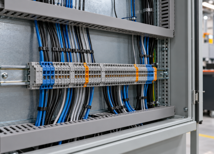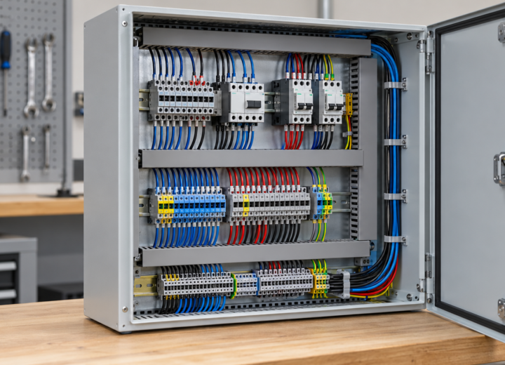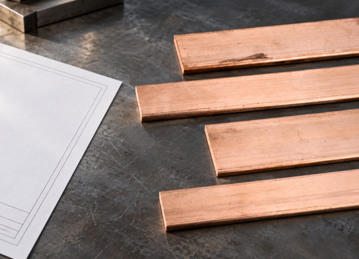
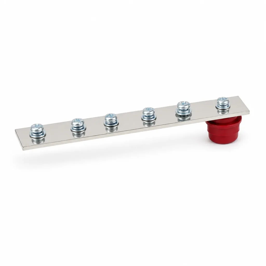
Summary: Grounding and neutral bars should be specified as separate functions, with their conductor destinations, mounting arrangement, connection points, and drawing references checked before cabinet fit-up. IEC 61439-1 provides a general rules and verification context for low-voltage switchgear and controlgear assemblies, but it does not certify an individual loose bar. A practical first action is to issue a terminal schedule and layout drawing that separately identifies protective-earth and neutral routes.
Grounding Copper Bus Bar and Neutral Copper Busbar serve different circuit functions
A grounding bar provides an organized point for protective-earth and bonding conductors, while a neutral bar provides a termination and distribution point for the neutral conductor in the applicable system design. Their apparent similarity can conceal a critical difference: they carry different circuit responsibilities and should not be selected merely by matching strip dimensions. Cabinet designers should begin with the circuit diagram, conductor schedule, and intended earthing arrangement.
For panel builders, separation supports clearer assembly and subsequent inspection. The relevant question is not whether both parts are copper, but whether each terminal position, mounting support, and route is identified for its intended conductor. In low-voltage assemblies, cabinet application requirements influence space, accessibility, and the number of outgoing connections; a shared visual convention alone is not a complete specification.
IEC 61439-1 is useful context because it addresses general rules and verification for low-voltage switchgear and controlgear assemblies. It should guide an enclosure-level conversation about design verification, rather than be presented as a certification of a separate copper strip. A drawing should therefore name the assembly function and provide enough information for the responsible engineering process to assess the actual cabinet.
A Grounding Busbar must remain segregated from the neutral conductor
A Grounding Busbar is commonly arranged so protective conductors can be landed, identified, and inspected without ambiguity. The appropriate physical relationship to the neutral bar depends on the electrical system and approved design, but the two functions need distinct references in drawings and wiring schedules. Treating a bonding point as an interchangeable neutral termination can create installation uncertainty even where the metalwork itself is sound.
Segregation can be expressed through position, terminal numbering, labeling, insulation supports, hardware selection, and conductor-routing notes. A useful review checks at least four interfaces: the incoming connection, outgoing terminations, enclosure bonding points, and the accessible test or inspection path. That review is especially valuable when a cabinet has multiple rows, field wiring, or parallel conductors competing for the same working space.
Misidentification can also increase lifecycle cost without appearing on the purchase line. Rework may involve relabeling, moving conductors, revising drawings, and repeating a fit-up inspection after other components are installed. An illustrative calculation is 12 terminations requiring 10 additional minutes each for correction: that is 120 minutes of assembly time before supervision, document control, or outage planning are considered. It is not a prediction of site cost.
Connection geometry determines Grounding Copper Bus Bar performance
Connection geometry starts with the actual conductor sizes, lug or terminal interface, hole pattern, fastening method, clearances, and available assembly access. A Grounding Copper Bus Bar may require custom length, drilling, bends, or mounting-hole positions to fit the enclosure rather than a generic stock pattern. Copper Development Association busbar guidance is helpful technical background, yet final dimensions and temperature rise require verified engineering in the actual enclosure.
Material condition and surface treatment also need a drawing callout when they affect the mating interface or storage environment. Procurement teams should avoid assuming a plating choice, insulation arrangement, or current capability from a photograph or a nominal width. The drawing should instead state the required material, finish where applicable, thickness, length, hole locations, tolerances, and the connection hardware or interface expected by the cabinet design.
The comparison below separates the selection dimensions that are often compressed into the phrase “copper bar.” It is a procurement and engineering review aid, not a substitution table. Values such as conductor count, enclosure temperature, fault-duty assumptions, and torque requirements must be supplied or confirmed by the responsible design authority before a part is released for production.
| Selection dimension | Grounding arrangement | Neutral arrangement | Documentation focus |
|---|---|---|---|
| Circuit function | Protective-earth and bonding connections | Neutral conductor terminations | Separate diagram reference and terminal designation |
| Routing objective | Accessible protective-conductor path | Orderly neutral distribution path | Route, entry, and service-clearance notes |
| Visual control | Grounding Busbar label or approved identifier | Neutral-specific label or approved identifier | Legend consistent with panel drawings |
| Commercial risk | Ambiguous bonding interfaces can cause rework | Ambiguous neutral positions can cause rework | Revision-controlled drawing and terminal schedule |
Documentation makes a Neutral Copper Busbar easier to inspect
A Neutral Copper Busbar should be documented as a connection system rather than only as a purchased component. The release package can show its part reference, location, material callout, hole pattern, support positions, terminal identifiers, and associated conductor schedule. A three-way check between schematic, general arrangement drawing, and bill of materials catches many reference errors before drilling, cutting, or final wiring begins.
Revision control is as important as the first issue. If a later change adds circuits, shifts a gland plate, or changes an incoming conductor interface, the bar drawing and terminal schedule should be reviewed together. For recurring cabinets, a controlled drawing revision reduces the chance that an older drilling pattern is combined with a newer wiring list. The required evidence remains the approved project documentation, not an informal verbal instruction.
The following matrix helps a buyer translate cabinet conditions into requests for information. It intentionally does not assign ampacity, fault withstand, or thermal values; those depend on verified assembly conditions. It does identify the information that allows an engineering team or drawing-based supplier to evaluate whether a standard form is suitable or a custom conductive part is needed.
| Cabinet situation | Information to define | Likely review emphasis | Evidence to retain |
|---|---|---|---|
| Compact control cabinet | Available length, support spacing, outgoing positions | Assembly access and conductor bend space | General arrangement and terminal schedule |
| Distribution cabinet | System arrangement, conductor interfaces, connection count | Neutral and protective-earth segregation | Schematic and approved connection detail |
| Drawing-based replacement | Existing dimensions, hole centers, material and finish callouts | Fit against the approved revision | Controlled drawing and sample approval record |
| Export-oriented assembly | Destination market and intended use | Applicable customer and regulatory requirements | Project compliance review record |
Selection of a Grounding Busbar requires an enclosure-level review
First, separate the functional requirement into a grounding schedule and a neutral schedule; record conductor types, positions, and the system reference before choosing dimensions. Second, issue a dimensional drawing that identifies length, thickness, width, hole centers, bends, supports, and finish requirements where applicable. Third, verify assembly access for tools, conductor bend radius, and inspection. These actions make the requirement reviewable before production instead of relying on later adjustment.
Fourth, identify the destination market and intended product use before making standards language part of a quotation or data sheet. Fifth, preserve the approved revision with the purchase record and the cabinet file. For drawing-based conductive parts, DONGYAO can review a drawing and manufacturing-service request against supplied dimensions and functional notes; the buyer should retain responsibility for the final assembly design and applicable verification.
Where a standard configuration is appropriate, procurement can specify a Grounding Copper Bus Bar by drawing reference, material requirement, dimensions, drilling pattern, and connection purpose rather than a broad product name. Where a separate neutral termination is required, the same release package should identify the relevant neutral-bar configuration. That approach gives suppliers a controlled basis for quotation and production without implying unverified electrical performance.
Standards language needs equally careful handling. OSHA 29 CFR 1910.303 applies within its United States regulatory scope and should not support a universal compliance claim. NEMA industrial-control standards may be relevant depending on the product and application, but their applicability does not create universal certification. IEEE 3001.2 is an IEEE recommended practice related to evaluating electrical service requirements; it is not a copper-bar product approval or a substitute for project engineering.
Frequently Asked Questions
Can a grounding bar and a neutral bar be the same copper strip?
They should not be treated as interchangeable simply because both are conductive copper components. Whether they may be connected or must remain separate depends on the electrical system, the approved circuit design, and applicable requirements. The practical action is to obtain a clear schematic reference and terminal schedule before fabrication or cabinet wiring begins.
What information should be on a grounding-bar drawing?
Include the part reference, material, dimensions, hole sizes and centers, bends, supports, surface requirement where applicable, and each connection’s intended function. The drawing should also identify the revision and the companion cabinet document it follows. Connection hardware, torque requirements, and conductor interfaces should be stated when the responsible design requires them.
Is IEC 61439-1 a certification for a loose copper bar?
No. IEC 61439-1 provides general rules and verification context for low-voltage switchgear and controlgear assemblies, not a standalone certification for an individual loose bar. A buyer should avoid transferring assembly-level language to a component unless supported by appropriate documentation and the actual scope of the applicable assessment.
How should a Neutral Copper Busbar be identified in a cabinet?
Use the approved project convention consistently across the schematic, terminal schedule, general arrangement drawing, and physical label. The identification should distinguish neutral terminations from protective-earth or bonding positions and remain legible during assembly and service. If the convention changes, update the linked documents through controlled revision rather than modifying only the cabinet label.
What should procurement ask a drawing-based supplier before ordering?
Provide the controlled drawing, desired quantity, material and finish requirements, mounting arrangement, hole pattern, and target delivery information. Also state whether the item is for grounding or neutral use, since that distinction affects documentation and review. Ask the supplier to identify any dimensional ambiguity before release, then retain the agreed drawing revision with the order.
References
- Copper Development Association, Busbar Applications
- IEC 61439-1, Low-voltage switchgear and controlgear assemblies
- OSHA 29 CFR 1910.303, General requirements
- NEMA, Industrial Control and Systems standards
- IEEE 3001.2, Recommended Practice for Evaluating Electrical Service Requirements
Specify the function first, document the interface second, and let the approved cabinet design determine the final conductive part. This principle keeps a familiar material from becoming an ambiguous component: the bar should follow the schematic, fit the enclosure, and retain a traceable relationship to the connection schedule throughout purchasing, assembly, inspection, and later maintenance.
For a restrained discussion of drawing-based copper parts for an electrical cabinet, contact DONGYAO with the current drawing revision and intended application. Providing conductor interfaces, mounting constraints, hole locations, material requirements, and the required quantity gives the conversation a practical starting point, while the buyer retains responsibility for final assembly engineering, verification, and project-specific compliance decisions.
For related conductor products, view the product categories.