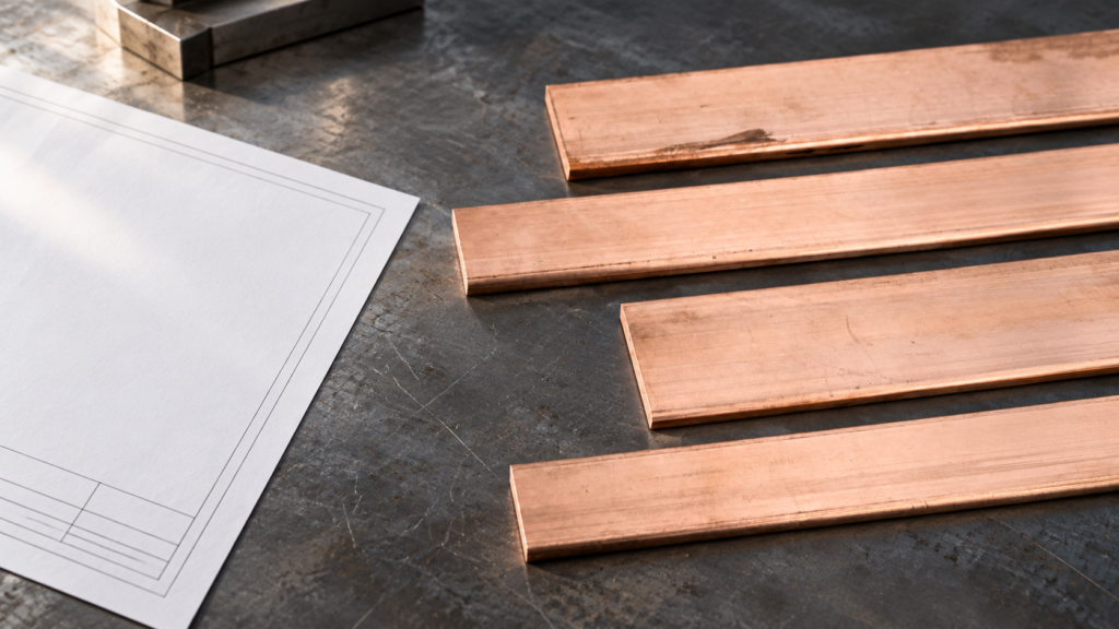
Summary: A grounding busbar protects equipment only within a continuous bonding and fault-current path: it connects exposed conductive parts and protective conductors to trigger proper fusing or breaker action during faults. NEC Article 250 governs grounding/bonding for relevant US electrical installations, while ASTM B187/B187M defines copper material specs, not installed fault protection. Define the full path, prospective fault capacity and clearing time, then inspect and test assembled connections.
How does a grounding busbar complete the equipment fault path?
A grounding busbar is a common protective-conductor termination in a panel, switchboard, or cabinet. It cannot replace the upstream conductor, source connection, or protective device. During an enclosure fault, the effective return path is normally through bonded conductors to the source, not through earth alone. A grounding bar makes those connections inspectable.
When a live conductor touches a bonded enclosure, current follows the conductive loop to its source. The bar joins enclosure bonds and protective conductors, while bonding reduces potential differences among accessible metal parts. The breaker or fuse, not the bar, interrupts the fault; prompt operation depends on loop impedance, current, device characteristics, and sound joints.
For an illustrative 5 kA fault lasting 0.1 second, I2t is 2.5 million A2s: a calculation example, not a bar rating. Evaluate actual conductor cross-section, joint heating, mechanical forces, and protective-device clearing time under applicable rules. More copper cannot compensate for a loose lug.
Which connections make the protective path dependable?
Trace the route on the drawing from each exposed conductive part through its bonding lead, lug, fastener, bar, upstream conductor, and source connection. Prepare the intended conductive contact surfaces; use the specified lug and hardware, and apply the assembly’s approved torque. Keep neutral and protective connections arranged only at code-permitted bonding points. A misplaced neutral-to-ground link can put normal return current on metalwork, even if the copper grounding busbar itself appears correctly sized.
How should a grounding bar be tested and inspected after installation?
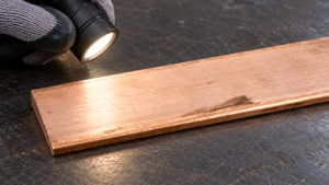
With equipment safely de-energized by qualified personnel, inspect for missing bonds, paint, burrs, loose lugs, corrosion, and conductor strain. Measure continuity from the metal part to the protective terminal using the project method; a four-wire test can resolve small joint resistances where specified. Record test points, instrument, criterion, and results. No universal milliohm limit applies: parallel paths and lead placement can distort a reading.
OSHA 29 CFR 1910.304 addresses wiring design and protection in applicable US workplaces. A continuity result reflects only that moment, not short-circuit withstand or future behavior. Reinspect accessible joints on the maintenance interval and after modifications, faults, or water ingress.
How does a copper grounding busbar compare with other bonding arrangements?
The useful comparison is the complete, maintainable assembly, not copper content alone. NEC Article 250 governs the grounding and bonding installation where adopted; no material choice independently proves compliance. A dedicated busbar usually makes conductor identification and maintenance simpler, while alternative arrangements can be appropriate if their bonding path is engineered and verifiable.
| Arrangement | Fault-path and access considerations | Durability and maintenance | Total-cost tendency |
|---|---|---|---|
| Dedicated copper grounding busbar | Defined termination point for multiple bonds; verify each lug and upstream connection. | Accessible joints aid inspection; copper still needs compatible hardware and corrosion control. | Fabrication and testing cost may be offset by easier identification and fewer rework hours. |
| Approved terminal or grounding block | Can suit compact assemblies when terminal ratings, conductor range, and installation are documented. | Follow the specified conductor preparation, torque, and inspection access. | Lower assembly complexity in some small panels; compare terminal and maintenance costs. |
| Cabinet frame or incidental fastener path | Only acceptable where the design and applicable rules explicitly establish the path; paint or removable joints can interrupt it. | More interfaces can complicate troubleshooting and later modifications. | Low apparent part cost can create high verification and rework cost. |
Which grounding busbar dimensions and interfaces belong on the drawing?
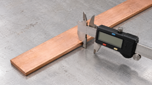
Use prospective fault current and clearing time to size the section and approve the connection layout. Width and thickness affect section and landing area; length and hole pitch affect clearance and access. Show units, tolerances, hole count and diameter, edge distances, bends, and finish. A copper grounding busbar also needs a grade and temper suitable for fabrication. ASTM B187/B187M may govern the purchased copper form, not the installed fault path.
| Dimension or feature | Protection-related reason | Evidence to approve |
|---|---|---|
| Width, thickness, and length | Influence fault duty, mounting fit, and room for distinct conductor landings. | Calculated duty, drawing tolerance, and measured finished part. |
| Hole diameter, pitch, and edge distance | Control lug seating, hardware clearance, and risk of damaged edges. | Lug schedule, drilling drawing, burr inspection, and fit check. |
| Connection count and conductor range | Prevent stacked or crowded terminations where the assembly does not permit them. | Terminal schedule and approved connection method. |
| Finish and mating metals | Set contact preparation and corrosion strategy at the actual interface. | Material designation, plating requirement if any, and installation instruction. |
| Mounting and enclosure clearance | Keep bonds identifiable, supported, accessible, and correctly isolated where required. | Assembly drawing and inspection access review. |
Compare the site’s electrical connection components with the drawing. Total cost includes fabrication scrap, hardware, testing, installation, and rework, not only unit price.
Which standards govern a grounding busbar and its installation?
NFPA 70 Article 250 addresses grounding and bonding where adopted; equipment instructions and the local authority may add requirements. OSHA 29 CFR 1910.304 addresses applicable US workplace wiring, not product certification. ASTM B187/B187M specifies copper forms for electrical purposes, not connected-system performance.
State edition and destination market. Request material designation, dimensional and lot records, connection instructions, and the assembly’s continuity and fault-duty plan. A bare-copper report cannot prove cabinet compliance; unsupported certification or fault-rating claims invite rejection and redesign.
How should a buyer select a grounding bar for equipment protection?
- Map the fault path. Identify the source, protective device, exposed metal parts, every bond, the upstream conductor, prospective current, and clearing time.
- Freeze the interface. Approve section, holes, lug and conductor range, fasteners, finish, mating metals, clearances, and inspection access on one drawing.
- Set measurable acceptance. Agree on material and dimensions, connection preparation and torque instructions, continuity method, and the evidence needed to demonstrate assembly fault duty.
- Qualify and maintain. Verify a representative assembled path before release, then retain drawings and test points for later maintenance and change control.
DONGYAO may be considered for a configurable copper bar against an approved drawing. Discuss dimensions, material, finish, and inspection records through the contact page, while final grounding design and approval remain with the responsible engineer and applicable authority.
Frequently Asked Questions
What Is a Grounding Busbar?
It is a conductive bar used as a common termination point for protective conductors and bonding connections. Its role depends on its installation in a complete grounding and bonding system. A bar alone cannot establish a fault-clearing path or certify an assembly.
What Does a Grounding Busbar Do?
It bonds designated metal parts and gives their protective conductors an organized, inspectable junction to the upstream fault-current path. Under a fault, that path helps deliver sufficient current for the appropriately selected protective device to operate. The bar itself neither detects nor interrupts the fault.
Where Is a Grounding Busbar Used?
Common locations include electrical cabinets, panelboards, switchboards, industrial controls, and equipment grounding networks. The actual arrangement depends on system design, enclosure construction, and local code. Confirm neutral isolation or bonding at the permitted point rather than copying another cabinet’s layout.
What Material Is Used for a Copper Grounding Busbar?
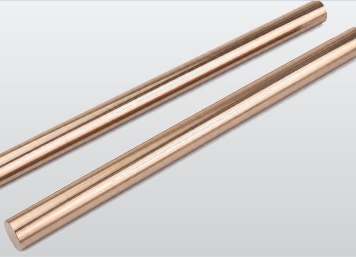
A copper grounding busbar uses a specified copper grade and temper appropriate to its electrical, fabrication, and environmental requirements. Bare or suitably finished copper may be selected according to the joint design and mating metals. Require a material designation and traceable evidence; color alone cannot establish chemistry, conductivity, or an installed fault rating.
Which references support grounding busbar decisions?
- NFPA 70, National Electrical Code
- OSHA 29 CFR 1910.304, Wiring design and protection
- ASTM B187/B187M-20, Standard Specification for Copper, Bar, Bus Bar, Rod, and Shapes for Electrical Purposes
Protective grounding is a system property: the best-looking bar is only as useful as its weakest connection and the device expected to clear the fault. For a drawing-led sourcing discussion, review DONGYAO’s copper grounding busbar options and contact the team with the bar dimensions, connection schedule, destination market, and verification requirements.
For related conductor products, view the product categories.