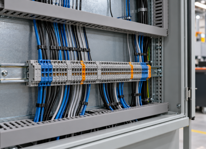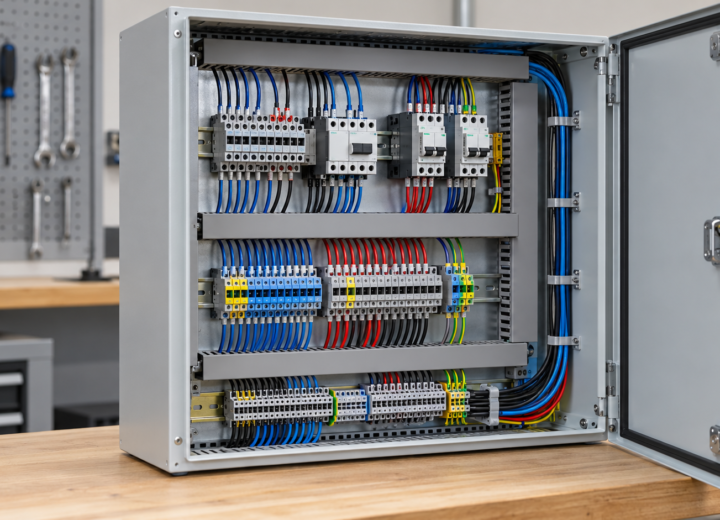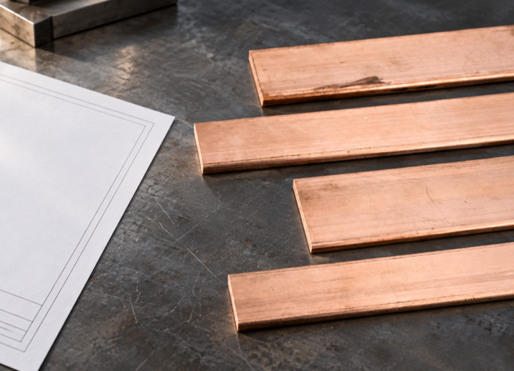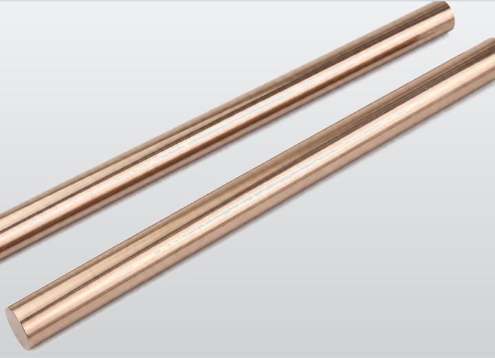
When a panel-builder in Suzhou replaced a corroded device surround during a battery-cabinet retrofit, he tightened the new plate, restored power, and saw the operator panel loosen again before the shift ended. The visible failure looked like a poor replacement part. Inspection showed a different cause: the mounting pattern, material temper, device geometry, and torque sequence had never been specified as one interface.
Summary: Brass switch plates are best selected as mechanical and electrical-interface parts, not as decorative covers. Verify the device pattern, plate thickness, substrate condition, environment, and installation standard before ordering. NEMA WD 6 addresses wiring-device dimensional guidance, while NFPA 70 and local adoption govern installation; neither automatically certifies a brass plate. For industrial panels, define the drawing, tolerances, finish, and inspection record before production.
Brass switch plates should be specified as part of the assembly
A plate around a switch, pilot device, disconnect control, or service point does more than conceal an opening. It locates the device, carries clamp load through fasteners, protects an edge, and presents information to the operator. In an industrial enclosure, those functions meet at a small area where a minor dimensional mismatch can become a recurring maintenance issue.
For brass switch plates, the engineering question is therefore not just whether the outline looks correct. It is whether every feature supports the installed device, the panel construction, and the intended maintenance action. That distinction prevents a nominally compatible cover from becoming a recurring fit-up problem.
The starting specification is the mating interface: device family, cutout diameter or rectangle, fixing-centre distance, thread form, panel thickness, and allowable rear-side clearance. Record dimensions in millimetres and identify the measurement datum. A caliper or coordinate-measurement inspection can confirm hole location, but the released drawing should state the tolerance rather than leave it to a sample.
A buyer requesting a Brass plate should therefore define whether it is a face plate, mounting plate, connection element, grounding-related part, or current-carrying component. Those roles have different critical characteristics. A visible plate may prioritize geometry and finish, while a conductive connection part also needs a stated current path, contact area, and joint preparation.
Thickness, stiffness, and fastener load are linked
Thickness is not a cosmetic number. A thin plate can dish around a device nut or screw head; an unnecessarily thick one can reduce thread engagement, interfere with a bezel, or create an awkward step at the enclosure. Treat stiffness as an assembly property influenced by unsupported span, hole spacing, temper, fastening method, and the adjoining panel.
Use the device maker’s torque instruction where it exists, and use a calibrated torque tool during a first-article build. The useful test is not simply whether a fastener reaches torque: it is whether the device remains aligned, the plate stays flat, and the assembly operates without binding after the specified tightening sequence. Record the tool range and sequence in the work instruction.
Conductivity does not remove interface risk
Brass is conductive, so an electrically live use requires deliberate separation, insulation coordination, and a documented current path. A decorative or mechanically mounted part must not become an unintended conductive bridge through burrs, loose hardware, or contact with adjacent terminals. The enclosure design, not the plate material alone, determines the electrical result.
Where the component forms part of an electrical connection, specify surface condition and contact preparation. Oxide, contamination, plating choices, washer stacks, and mixed-metal joints can affect contact resistance over time. An illustrative incoming check may include visual examination, dimensional measurement, and a joint-resistance test defined by the customer’s assembly plan; the acceptable value must come from that plan, not from a generic article.
Brass plates must be selected by environment and interface
Define the operating environment early. Indoor panels, washdown-adjacent equipment, coastal installations, and energy-storage cabinets impose different corrosion and contamination conditions, especially where an exposed edge or conductive function is involved.
For custom connection work, a drawing should identify base material, finish, edge treatment, flatness expectation, and marking method. This avoids treating a material callout as if it fully describes a finished part.
For assemblies involving larger battery connections, engineers can compare the required geometry with this brass connector piece for large-format lithium systems before turning a generic plate request into a production drawing. The useful question is whether the part is only a cover or carries a defined electrical and mechanical duty.
Finish and edge control deserve an explicit note
Specify the required surface condition, finish, and edge treatment instead of relying on a hotograph. A sharp edge can damage insulation, impede a gasket, or create a service hazard; define which edges must be broken and which holes must be burr-free. Approve a representative sample when appearance or contact preparation is critical.
A comparison clarifies where brass switch plates fit
The comparison below is a screening tool. Actual performance depends on alloy, thickness, finish, forming, and the installed assembly; for current-carrying parts, review the complete conductive path rather than comparing only base metals.
| Material option | Useful tendency | Typical watchpoint | Inspection focus |
|---|---|---|---|
| Brass alloy | Machinable conductive metallic substrate; suitable for specified interface parts | Alloy, finish, and mixed-metal environment must be defined | Dimensions, flatness, burrs, surface condition |
| Copper alloy | Often considered when a defined conductive path is central | Softness, oxidation, and joint design may govern the result | Contact faces, thickness, joint-resistance method |
| Stainless steel | Often selected for mechanical exposure and corrosion considerations | Electrical function and finish require separate assessment | Passivation/finish requirement, edge condition, hardware pairing |
| Coated steel | Common structural-panel option with broad fabrication availability | Cut edges and coating damage need control | Coating coverage, cutout quality, grounding arrangement |
| Engineering polymer | Useful where insulation and low mass are primary needs | Temperature, UV, impact, and fastening creep must be checked | Material grade, moulded geometry, crack inspection |
Total cost includes more than unit price. Compare incoming inspection time, assembly minutes, expected rework, and line-hold risk—not just material cost. Hole drift, damaged wiring, or inconsistent finish can erase a small purchase-price saving.
Require a traceable lot record against the approved drawing revision and incoming checks.
Application conditions determine the right Brass plate specification
Separate the application class before seeking quotations. The table turns common operating situations into information that a supplier can quote and an incoming inspector can verify. It deliberately does not assign universal thicknesses or current ratings, because these must be tied to the device, drawing, and circuit design.
| Application condition | Specify before purchase | Build or inspection action |
|---|---|---|
| Indoor control-panel device surround | Device pattern, panel thickness, visible finish, fixing hardware | Trial-fit first article; check alignment and operating clearance |
| Energy-storage cabinet connection area | Electrical role, creepage/clearance design, contact surfaces, insulation arrangement | Review against the approved electrical drawing and joint process |
| High-humidity or coastal equipment | Exposure description, finish, dissimilar-metal interfaces, service interval | Approve representative surface condition and protect cut edges |
| Serviceable machine enclosure | Access frequency, label area, edge treatment, replacement interchangeability | Verify tool access and repeatable reinstallation |
| Grounding or bonding-related hardware | Defined bonding path, hardware stack, coating removal requirement, verification method | Use the project’s documented continuity or bonding procedure |
When a design includes grounding bars or multi-material interfaces, the mating-system definition is as important as the plate drawing. This customized multi-material grounding copper bar is a relevant reference point for discussing material interfaces, but the project engineer should still establish the bonding method and acceptance procedure.
Standards guide installation and workplace safety, not automatic product approval
NEMA WD 6 provides dimensional specifications and guidance for wiring devices; use it when the device interface falls within its scope, and verify the applicable edition and device category. It is not a blanket certification of every plate material or custom cover. A custom plate can match a device pattern yet still require separate review of its enclosure, fastening, and electrical role.
NFPA 70, the National Electrical Code, addresses electrical installation in the United States when adopted by the authority having jurisdiction; local adoption and amendments control the enforceable requirements. For export or non-US projects, identify the destination-market rules instead of applying a US code label generically. Installation compliance belongs to the installed system and its documented design.
OSHA electrical provisions and the corresponding eCFR workplace rules establish safety duties for covered workplaces, including requirements associated with electrical equipment and installation. OSHA 1910.303 and 1910.305 should not be used as marketing proof that a custom brass part is approved. Claims must match the product’s actual evidence, intended use, and applicable certification route.
Specify brass switch plates with a controlled procurement checklist
First, issue a revision-controlled drawing with dimensions, hole centres, datum scheme, thickness, material, finish, edge condition, and marking requirements. Add the mating device drawing or part number.
For repeat orders of brass switch plates, retain the approved first-article record and reference sample. It gives purchasing and quality teams a common basis for detecting changes before assembly.
Second, define the electrical boundary. State plainly whether the part is non-current-carrying, part of a bonding arrangement, or part of a conductive connection. For the latter two cases, include the hardware stack, contact preparation, insulation arrangement, and the project-specific verification method.
Third, request a first article before a production lot when a plate is custom, operator-visible, or coupled to a tight device pattern. Measure critical features with a documented method, verify fit in the intended enclosure, and retain the approved sample or inspection record. This controls variation before it becomes field rework.
Fourth, assess supplier capability against the required configuration. DONGYAO can be considered for configurable electrical connection components alongside its DC contactor, shunt, and hydraulic circuit-breaker portfolio. For a material-format reference, review this brass plates material-format listing against the released design.
A second Brass plate from the same nominal material can behave differently if thickness, temper, hole layout, or finishing route changes. Lock those variables into the purchase order and inspection plan. That is usually more valuable than asking for a broad assurance that the part is “industrial grade.”
FAQ
What is a brass switch plate?
A brass switch plate is a formed or machined brass component placed around a switch or related control-device opening. It may provide positioning, protection of the cutout edge, a finished service surface, or a defined mounting interface. Its exact function should be stated on the assembly drawing.
Are brass light switch plates wall mountable?
They can be wall mountable when their hole pattern, device type, wall-box arrangement, and fasteners match the installed wiring device. In industrial settings, confirm clearance behind the plate and that tightening the hardware does not distort the device or enclosure. Do not assume a decorative residential pattern fits a panel-mounted control.
What is the best brass light switch plate?
The best choice is the one that matches the device geometry, environment, finish expectation, and mounting method of the project. For a controlled panel build, a drawing-backed custom part may be preferable to a general-purpose cover because its tolerances and inspection points are known. “Best” should be judged against fit and lifecycle work, not appearance alone.
Does brass light switch plates ship?
Brass light switch plates can be shipped, but packaging should protect visible faces, edges, and flatness during transport. Confirm quantity per package, protective film or separators where needed, destination, and any import documentation before release. Custom parts should also be identified by drawing revision on the packing record.
Why should you choose brass plates?
Choose brass plates when their machinability, metallic appearance, or required conductive-interface characteristics fit the defined assembly. The decision still depends on alloy, finish, exposure, fastening, and whether the part has an electrical role. Compare the full installed interface rather than selecting solely by colour or base-metal name.
Where can I buy brass sheet & plate?
Buy brass sheet and plate from a supplier that can identify the material, supplied form, dimensions, and any requested processing or inspection evidence. If you need a finished device interface rather than stock material, provide a controlled drawing and the mating-device information. That separates a sheet purchase from a finished-part procurement decision.
References
- NEMA WD 6: Wiring Devices—Dimensional Specifications
- NFPA 70: National Electrical Code
- eCFR Title 29, Part 1910, Subpart S—Electrical
- OSHA 1910.303—General Requirements
- OSHA 1910.305—Wiring Methods, Components, and Equipment for General Use
The dependable choice is the one whose material, geometry, interface, and verification method all appear in the same controlled record. For a project-specific discussion of connection components or a drawing review, contact DONGYAO with the device layout, operating environment, and required inspection points.
For related conductor products, view the product categories.