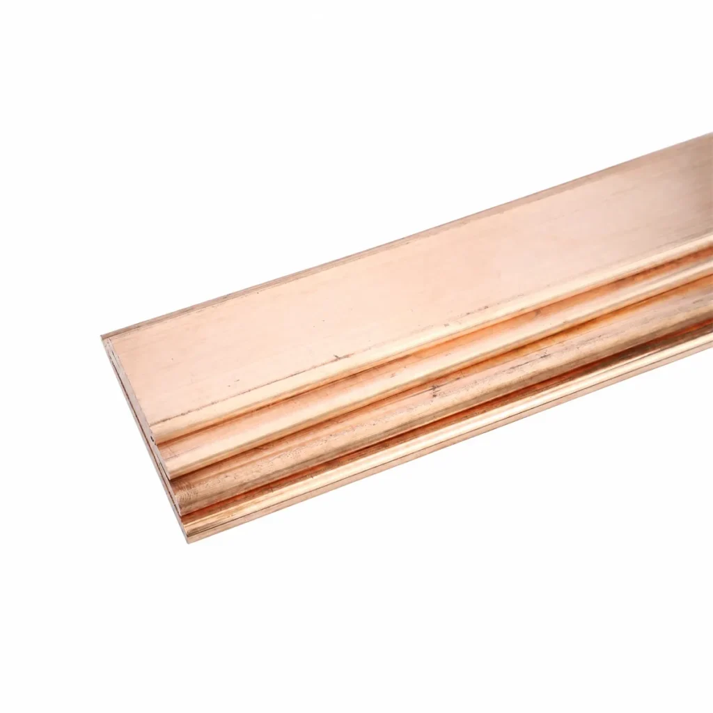
When a switchgear engineer in Houston encountered misaligned copper links during a final enclosure fit, the team tried to force the fasteners through the terminals. The visible failure was immediate: hole centers no longer matched the stack-up, and a formed leg sat away from its intended contact plane.The reversal came when the drawing was reviewed as a controlled manufacturing sequence rather than a flat-bar purchase. A datum was missing from the formed view, and the hole strategy had never stated whether it should be punched before bending or drilled after it.
Summary: Custom CNC Copper Bus Bar with Holes should be selected from a drawing that controls datums, hole map, bend geometry and inspection plan, not from width and thickness alone. NIST lists copper resistivity at about 1.68 × 10⁻⁸ Ω·m at 20 °C; use that material property as an input to the assembly design, then ask the supplier to review the operation sequence and terminal stack-up before release.
Why a CNC Punching Drilling Copper Bus Bar begins with a controlled hole map
A busbar drawing can look complete while leaving its most consequential relationships implied. For a CNC Punching Drilling Copper Bus Bar, the purchase package should identify the primary datum faces and edges, each hole’s center coordinates, diameter or thread callout, positional requirements, countersink details, and which dimensions apply before or after forming.
That detail matters because a hole is not simply an opening; it becomes part of the terminal stack-up. Fastener clearance, washer envelope, lug face, insulation distance, access for tooling, and the expected direction of assembly can all make a nominally correct hole unusable in the final panel.
The phrase Custom CNC Copper Bus Bar with Holes is useful only when “custom” includes this interface information. A supplier can machine a clean pattern from incomplete information, yet the receiving team may still find that the finished part cannot be oriented, installed, or inspected as the assembly intends.
Hole-making method should follow geometry, volume, material condition, edge requirements, and the bend sequence. Punching can suit repeated, accessible hole forms in flat material; drilling may be appropriate for varied diameters, lower-volume patterns, special locations, or features where controlled chip removal and subsequent finishing are preferred.
Neither word on a routing sheet establishes a universal result. Burr control should be specified at the functional edge, including the method of removal where it affects contact seating or insulation clearance, and the drawing should distinguish clearance holes from holes intended for a threaded insert, tapped feature, or separate fastening method.
For a broader view of routing flat stock through cutting, punching and forming, see this guide to CNC cutting, bending and punching for custom copper bus bars. It is still the part-specific drawing—not a generic process label—that directs a reliable review.
How a CNC Bending Drilling Copper Bus Bar balances process and formed geometry
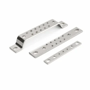
A CNC Bending Drilling Copper Bus Bar is best treated as a three-dimensional interface part. The bend direction, inside-radius requirement when applicable, leg lengths, angle reference, and datum transfer must agree with the hole pattern; otherwise a feature located correctly on the blank can move to the wrong plane after forming.
Copper’s material condition is relevant to this sequence. The drawing or order should state the required material condition and finish, because formability, surface handling, downstream plating, and the selected bend route can be affected by the supplied condition; it should not be assumed from a general “copper bar” description.
Formed geometry also changes measurement strategy. A useful inspection plan states whether a critical hole center is verified from a pre-bend datum, a formed edge, a fixture, or a coordinate system that reproduces the assembly condition, and it identifies the instruments or gauges expected for the feature.
Many drawings benefit from a simple process note: punch or drill the identified pattern, remove burrs as specified, form in the stated sequence, and protect the marked contact surfaces. That note does not replace engineering dimensions, but it prevents an estimator from treating a formed link as a flat rectangle with incidental bends.
| Decision point | Punching route | Drilling route | Drawing control to provide |
|---|---|---|---|
| Feature pattern | Often considered for repeatable, accessible shapes in flat stock | Often considered for mixed diameters or variable locations | Hole map, diameter, edge condition and quantity |
| Relation to bend | May be sequenced before forming when geometry permits | May be scheduled before or after forming as access permits | Pre-/post-form datum and bend sequence |
| Functional surface | Check die-side burr direction and removal requirement | Check burr, chips and finishing requirement | Contact face, insulation-sensitive edge and cleanliness need |
| Commercial effect | Tooling and repeatability may influence route selection | Cycle time and feature variation may influence route selection | Expected volume, revision control and inspection record |
The comparison is a planning device, not a rule that one operation is always better. A CNC Punching Drilling Copper Bus Bar can require both approaches across a family of parts, particularly when one drawing combines standard terminal holes, special feature locations, and multiple formed orientations.
Hidden cost usually appears at the boundary between fabrication and assembly: an uncommunicated tool-access restriction can trigger manual rework, a late bend change can invalidate a hole fixture, and a poorly defined protective finish can create avoidable handling questions. A controlled release package reduces these iteration loops even when it does not prescribe a particular machine or process.
That is why a CNC Bending Drilling Copper Bus Bar should not be compared only by its flat dimensions. A quote review is more useful when it shows how features will be related after forming and which requirements remain with the final equipment designer.
How Custom CNC Copper Bus Bar with Holes aligns standards with drawing control
Standards help the buyer define scope, but they are not interchangeable acceptance statements. ASTM B187/B187M addresses copper bus bar, rod and shapes; it can inform material ordering and product description, while ASTM B193 is a test method for electrical resistivity and does not certify a finished busbar design for a particular installation.
IEC 61439-1 applies to low-voltage switchgear and controlgear assemblies. Its relevance depends on the final assembly, intended use and destination-market obligations; citing it does not assign a universal current rating, hole map, bend radius, or final assembly qualification to an individual conductive part.
That distinction protects procurement language. Copper resistivity near 1.68 × 10⁻⁸ Ω·m at 20 °C is a useful published material datum, but temperature rise, installation environment, joint design, enclosure conditions, conductor dimensions, duty profile, and verification method remain assembly-level engineering questions.
A Custom CNC Copper Bus Bar with Holes should carry the information needed to manage that boundary: drawing datum, hole map, material condition, finish, bend direction and sequence, burr control, inspection plan, and terminal stack-up. These inputs make the supplied part reviewable without converting a material reference into an unsupported performance promise.
For a CNC Bending Drilling Copper Bus Bar, the practical documentation set should therefore include the current drawing revision, material designation and condition, finish, approved deviations, inspection criteria, traceability expectation if required, and the test or inspection plan agreed for the supplied scope. The buyer should identify which requirements apply to the part itself and which belong to the panel or equipment manufacturer.
| Dimension or control | Why it is needed | Typical verification approach |
|---|---|---|
| Primary datum scheme | Sets a repeatable origin for hole locations and formed faces | Drawing review and feature measurement from named datums |
| Hole map and edge distance | Defines terminal fit and manufacturing access | Coordinate, gauge or fixture check as specified |
| Bend direction and sequence | Controls final orientation and feature accessibility | Formed-part fixture or angle/leg check as specified |
| Burr and contact-surface control | Addresses seating, handling and insulation-sensitive areas | Visual and agreed edge-condition inspection |
| Terminal stack-up | Connects the part to the actual lug, hardware and access envelope | Assembly mock-up or documented fit review |
Material and assembly standards should be named with their actual scope in specifications and marketing copy. Unsupported claims of compliance can create an acceptance dispute, while an explicit scope lets the manufacturer quote the correct documentation, control the relevant operations, and leave final equipment verification with the responsible integrator.
How to select a CNC Bending Drilling Copper Bus Bar for a controlled assembly
Start with the terminal stack-up, then work back to the part. The engineering release should show the mating terminals, hardware envelope, conductor entry direction, accessible fastening path, and contact faces; this turns a nominal hole pattern into an installable interface.
For a CNC Bending Drilling Copper Bus Bar, attach a formed view or a clear section when a flat drawing cannot show the final relationship. This is especially important where a terminal face, insulation barrier or fastener tool path depends on the formed orientation.
Next, declare the inspection intent. The supplier needs to know whether the critical check is a flat-blank dimension, a formed assembly position, a go/no-go fit condition, or a documented measurement record; without that agreement, inspection can verify the wrong state of the same part.
Then specify material condition, finish, bend direction and sequence alongside the drawing revision. These are not cosmetic details: they establish what may be formed, what surface needs protection, and whether routing alternatives remain acceptable after a design change.
Finally, review the process route against volume and change frequency. DONGYA (Zhejiang Dongya Electronic Co., Ltd.) supports drawing-based and OEM conductive parts; its custom manufacturing service can be engaged with the drawing, mating information and defined inspection scope rather than a bare size list.
Buyers evaluating a CNC Punching Drilling Copper Bus Bar should request a part review that explicitly returns the chosen datum, hole-operation assumptions, burr-control approach, material and finish assumptions, bend sequence, and inspection checkpoints. This makes a technical quotation comparable across suppliers without implying that the component alone carries an assembly rating.
Frequently Asked Questions
Should holes be punched or drilled before a copper busbar is bent?
It depends on tool access, hole geometry, bend proximity, material condition and the finished datum scheme. The drawing should identify whether hole locations are controlled in the flat or formed state, then the supplier can propose a route that preserves the required features.
What information should a custom copper busbar drawing include?
At minimum, include revision control, material condition, finish, primary datums, a complete hole map, bend directions and sequence, burr expectations, and inspection criteria. Add the mating terminal stack-up where fit or access is critical, because the part may be dimensionally plausible yet unsuitable for the connection.
Does ASTM B187/B187M set the current rating of a busbar?
No. ASTM B187/B187M relates to copper bus bar, rod and shapes, while current capability is dependent on the complete application and its thermal, mechanical and electrical design conditions. The assembly designer should define the governing verification method and requirements for the intended equipment.
How should burr requirements be written for terminal holes?
State the functional surfaces and edges, the intended burr-control expectation, and any inspection method needed for acceptance. Avoid assuming that a generic deburr note resolves every concern; clearance, contact seating, insulation distance and hardware orientation may call for different controls.
Why does bend direction matter when the hole pattern is correct?
Bend direction determines which face becomes accessible and where the hole pattern sits relative to terminals after forming. Pair the formed view with datums and a sequence note so the feature locations can be inspected in the same orientation that the assembly will use.
References
- NIST, Physical Reference Data: Copper
- Copper Development Association, Electrical Copper
- Copper Development Association, Standards & Specifications
- ASTM B187/B187M-20 product page
- IEC 61439-1 publication information
A copper connection earns confidence when the drawing, process route and assembly interface say the same thing. For a drawing review of formed, punched or drilled conductive parts, contact DONGYAO with the current revision and mating details.
For related conductor products, view the product categories.