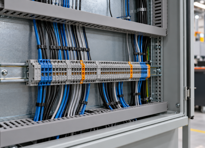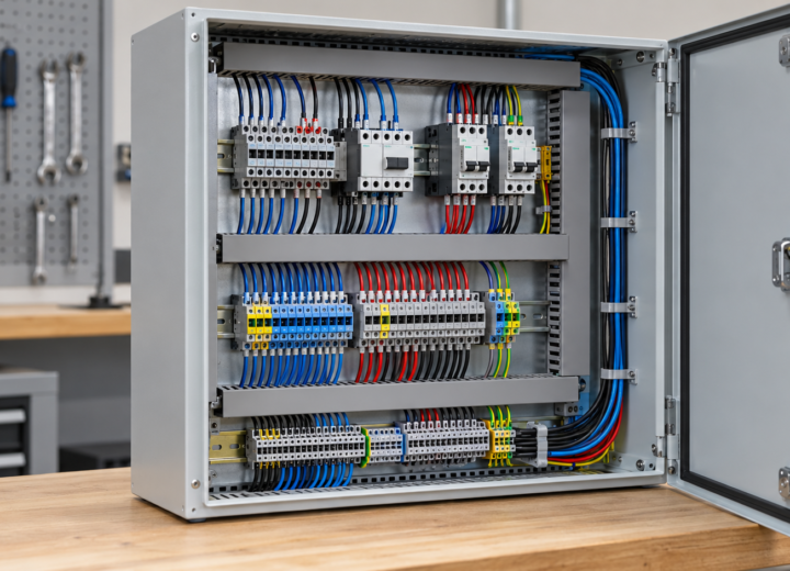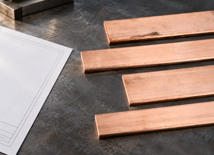
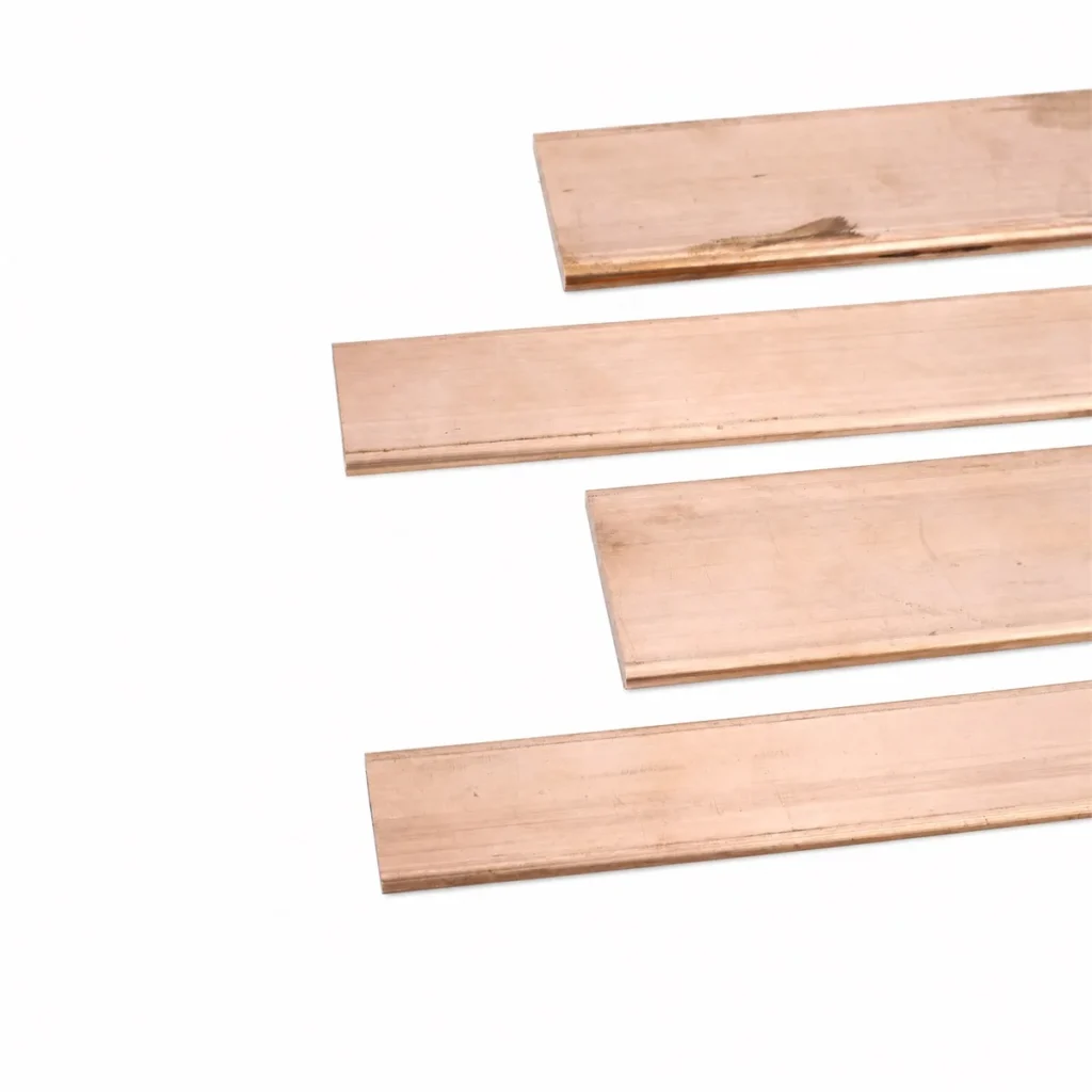
When a controls engineer in Houston releases a cabinet drawing after checking only the nominal cross-section, the quotation can look complete while the busbar is still underspecified. Hole positions may conflict with the terminal pitch, a bend may not clear the enclosure, and the plating note may be missing from the released revision. The late correction is rarely caused by poor copper; it is caused by an incomplete interface definition.
Summary: A reliable custom-shape copper busbar starts with a material designation covered by ASTM B187/B187M, then defines the sectional geometry, formed features, joint interfaces, surface condition, and verification route. IEC 61439-1 and IEC 61439-2 apply to the low-voltage assembly in which the conductor is used; they do not provide one universal busbar size or current rating. The practical action is to release a drawing that separates material requirements from assembly verification.
A custom copper busbar specification should begin with the assembly duty.
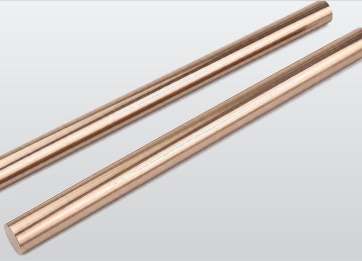
ASTM B187/B187M covers copper bus bar, rod, and shapes, so it provides a credible material-reference point for a fabricated conductor. It does not replace the part drawing. The drawing still needs to state the requested copper designation, temper or condition where applicable, supplied form, and any finish requirement that affects a joint or exposed surface.
IEC 61439-1 establishes general rules for low-voltage switchgear and controlgear assemblies, while IEC 61439-2 addresses power switchgear and controlgear assemblies. In engineering review, that means the assembly duty is assessed at assembly level rather than inferred from a generic bar dimension. A current value copied from another cabinet is not a substitute for design verification.
For this reason, a quotation request should identify the environment, enclosure arrangement, connection method, and service function before a custom copper bus bar is priced. Where the project uses neutral or protective-conductor functions, the relevant connection arrangement should be stated separately from the main power path rather than assumed from a shared material note.
That distinction matters on a custom copper busbar project because material, geometry, and assembly duty are reviewed by different people at different times. Purchasing needs an unambiguous scope, the fabricator needs a manufacturable drawing, and the panel-builder needs evidence that the finished assembly can be verified. The drawing must carry those decisions together.
The distinction prevents a common procurement error: treating a copper conductor as an isolated commodity after it has become part of a switchgear assembly. The copper busbar material range is the starting point, but the released part must also reflect the enclosure, terminals, fasteners, clearances, and application duty that govern the finished installation.
Material and geometry should be released as separate decisions.
The material callout describes what is to be supplied; the geometry describes how that material becomes a conductor part. A clear release normally distinguishes width and thickness, overall length, edge condition, hole pattern, bend sequence, and surface treatment. This separation makes revisions traceable when the cabinet interface changes but the material basis does not.
For applications that combine busbars with cabinet terminals, the copper busbar sourcing notes for cabinet projects provide a useful reminder: terminal pitch, tightening access, and packing orientation can affect the accepted part as directly as the nominal bar section. Those details belong in the controlled drawing and purchase specification.
A custom copper busbar drawing should separate material, geometry, and interfaces.
The most stable drawings use one field for the material reference, one for dimensions and forming, and one for the mating interfaces. This is not paperwork for its own sake. It stops a fabricator from treating a functional feature as a cosmetic note, and it stops the project team from discovering an inaccessible fastener after the bar has been formed.
Hole diameter, center distance, countersink or thread detail, and bend orientation should be called out from a fixed datum. The drawing should also identify which face contacts the terminal or lug. Without that reference, two visually similar custom-shape busbars can place the contact face on opposite sides and create an avoidable rework loop at assembly.
| Specification field | Standards-based engineering purpose | Release note |
|---|---|---|
| Material designation | Links the supplied copper bus bar, rod, or shape to ASTM B187/B187M. | State the requested designation and supplied condition. |
| Section and form | Defines the manufactured conductor geometry; IEC 61439 does not prescribe a universal section. | Control dimensions, datums, bends, and edge condition on the drawing. |
| Joint interface | Supports assembly verification under IEC 61439-1/-2. | Identify contact face, hole pattern, hardware access, and finish. |
| Assembly duty | Places the conductor within the relevant low-voltage assembly design. | Record enclosure, function, environment, and verification responsibility. |
The table is deliberately a release checklist rather than a generic performance chart. ASTM B187/B187M defines the material scope, and IEC 61439 defines the assembly verification context. Neither document should be used to invent a current rating, bend radius, or temperature-rise result without the actual project design inputs and the applicable verification method.
A custom copper busbar comparison table makes the verification route visible.
Custom-shape work becomes more predictable when the project team distinguishes an unformed copper blank from a finished conductor part. The blank may satisfy a material requirement, while the finished part still has to fit its terminal interfaces and operate within the verified assembly. That difference is especially important where several parts share one cabinet compartment.
| Project stage | Primary question | Evidence to retain |
|---|---|---|
| Material selection | Is the copper form within the requested ASTM material scope? | Material designation and supplier documentation. |
| Fabrication release | Can the shape, drilling, and forming be made from the controlled drawing? | Approved drawing revision and inspection plan. |
| Assembly integration | Does the part match the terminal and enclosure interfaces? | Assembly drawing, connection details, and verification record. |
| Project acceptance | Is the low-voltage assembly assessed to its applicable IEC 61439 route? | Defined verification responsibility for the complete assembly. |
For neutral and grounding functions, the relevant neutral bar and grounding connection parts should be treated as their own interface family. The material may be similar, but the connection duty and terminal arrangement are different. Combining those notes into one vague “copper strip” instruction makes later inspection more difficult than necessary.
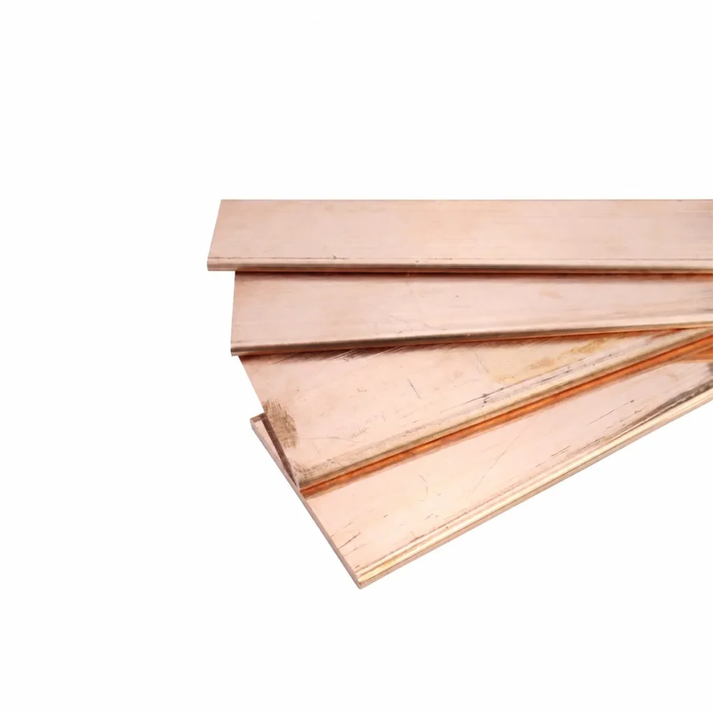
A custom copper busbar must match the application environment before release.
The same material can serve different functions in a distribution cabinet, a data-center panel, a communication enclosure, or rail-transit equipment. The application changes the requested interfaces, mounting constraints, and verification route. It does not justify copying a performance value from another project, because the complete assembly configuration remains the governing design condition.
Environmental notes should identify exposure that affects the specified surface condition and the joint arrangement. Installation access should identify whether tools can reach the required connections after adjacent equipment is fitted. These are practical controls, yet they have direct technical value because IEC 61439 verification is concerned with the completed assembly rather than a loose conductor on a bench.
| Application condition | Custom busbar decision | Why the decision is controlled |
|---|---|---|
| Cabinet power distribution | Define terminal interfaces and enclosure route. | The conductor is part of a power assembly under IEC 61439-2. |
| Neutral or grounding connection | Define terminal type and connection layout separately. | Function and inspection points differ from the main power path. |
| Drawing-based replacement part | Confirm the revision, datum, and mating component. | Visual similarity does not guarantee interchangeability. |
A custom copper busbar should be specified against the correct standards.
ASTM B187/B187M and IEC 61439 answer different questions, and using them correctly is more useful than citing a long list of unrelated standards. ASTM B187/B187M concerns copper bus bar, rod, and shapes. IEC 61439-1 and IEC 61439-2 concern the design and verification of the low-voltage assembly that incorporates the conductor.
That boundary should be written into the project record. The material standard supports the copper-product requirement; the IEC documents support the assembly-level verification framework. If a project requires a calculated current rating, dielectric arrangement, temperature-rise assessment, or short-circuit performance, those inputs and the responsible assembly designer must be identified rather than inferred from the bar alone.
This approach keeps the technical file auditable. It also prevents a supplier from making unsupported claims about an unfinished system. A custom shape copper bus bar can be manufactured to a controlled drawing, but a claim about the final cabinet must be supported by the applicable assembly design and verification evidence.
A custom copper busbar procurement review prevents drawing changes after release.
Before release, the purchasing package should be read as an interface document rather than a material request. The buyer should verify that the latest drawing revision matches the bill of materials, that every hole and formed feature has a datum, and that the requested surface condition is consistent with the intended connection method. These checks usually take less time than one corrected production lot.
The technical reviewer should also identify the owner of assembly verification. The fabricator can confirm conformity to the supplied drawing and agreed material requirement, while the assembly designer controls the evidence associated with IEC 61439. Keeping those responsibilities separate avoids ambiguous statements in quotations, inspection records, and handover documents.
Where the requirement includes grounding bars or mixed connection parts, the custom grounding copper bar configuration can be used as a product reference, then adjusted through the project drawing. The correct release point is the approved interface, not a catalog image or a previous cabinet layout.
Custom copper busbar questions should be resolved before production.
What should a custom copper busbar drawing state before quotation?
It should state the material reference, controlled dimensions, hole and bend details, datums, joint faces, requested surface condition, quantity, packing needs, and the mating application. The drawing should also identify the revision that governs production. Those details allow the fabricator to assess manufacturability without making assumptions about interfaces.
Does ASTM B187/B187M set the final busbar dimensions?
No. ASTM B187/B187M defines the scope for copper bus bar, rod, and shapes; the released part dimensions remain a project design requirement. The purchaser should provide the section, length, holes, bends, and tolerances needed for the actual assembly instead of expecting a universal electrical-cabinet geometry from the material standard.
Does IEC 61439 define one current rating for every copper busbar?
No. IEC 61439 addresses the low-voltage assembly and its verification framework. The relevant conductor performance depends on the assembly configuration, enclosure, connections, environment, and applicable verification approach. A generic rating copied from another project is not sufficient technical evidence for a different cabinet.
When is a prototype or verification sample useful?
A sample is useful when a drawing introduces a new bend sequence, terminal interface, plating requirement, or tight installation clearance. It can confirm the physical fit before a production release. It does not replace the complete assembly verification responsibilities that apply to the final low-voltage equipment.
Can a grounding bar and a power busbar use the same drawing format?
They can use the same drawing discipline, but they should not be treated as the same function. The drawing should separately identify the connection duty, terminal layout, contact faces, and inspection requirements. That separation makes the assembly documentation clearer and reduces the risk of fitting the correct material in the wrong location.
Reference
The engineering decision is not simply whether a bar is copper. It is whether the material reference, controlled shape, connection interfaces, and assembly evidence point to the same released part. Dongyao supports that review with drawing-based copper conductor supply for the point at which a requirement has to become a manufacturable electrical component.
For related conductor products, view the product categories.