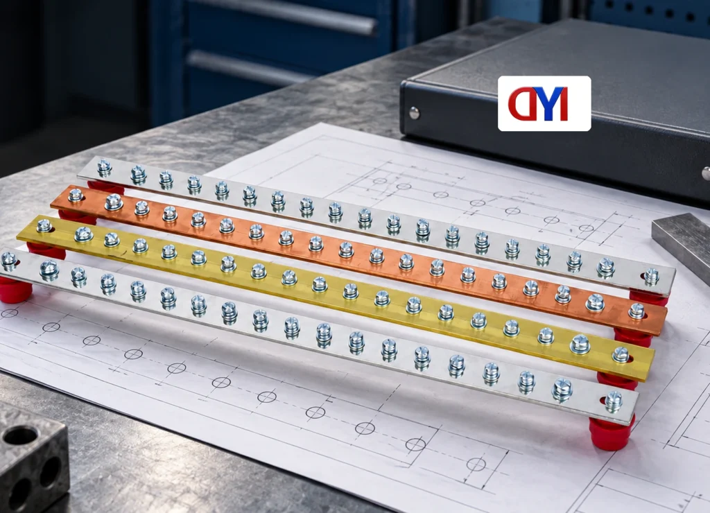
When an assembly engineer in Glasgow, Noah, encountered a copper strip that fitted the mounting holes but cracked during repeated movement, the hole pattern initially seemed correct. In this illustrative scenario, a rigid punched strip had been treated as a qualified flexible connection. The correction was to define the movement duty and connection construction before ordering.
Summary: Process copper strips according to the provided drawings, with controlled hole geometry, burr limits and material condition. Perforations change the remaining section; a thin or perforated strip does not automatically have a fatigue rating. Specify a flexible copper connection by movement, terminations and qualification evidence, not by appearance alone.
Define each hole from a controlled datum
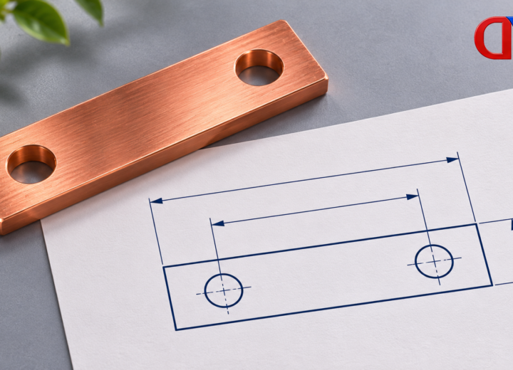
Custom-made perforated copper strips need hole diameter, pitch, end distance and position relative to meaningful datums. Show whether dimensions are center-to-center or from an edge. Identify slots, countersinks and other features separately rather than leaving the supplier to infer them from an image.
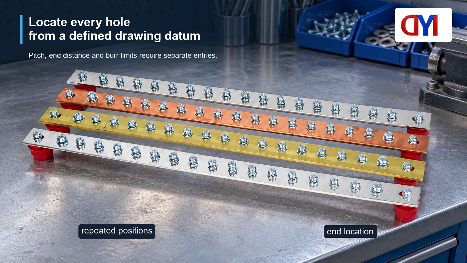
A drawing can locate each hole from one datum or use another appropriate dimensioning scheme. A chain of pitch dimensions may accumulate variation at the far end. The drawing owner should select controls that preserve the mating assembly’s fit. Do not enlarge holes at installation to resolve an unapproved mismatch.
ASTM B187/B187M and ASTM B152/B152M address different copper stock forms. Select the relevant material/product framework, then add the fabricated feature requirements. A compliant raw strip does not establish that the punched part matches the customer drawing.
| Feature | Drawing requirement | Inspection concern |
|---|---|---|
| Hole | Diameter and tolerance | Fastener or lug fit |
| Pattern | Position/pitch and datum | Accumulated mismatch |
| Ends | End distance and cut length | Remaining material and mating envelope |
| Edges | Burr limit and edge condition | Contact, insulation and handling |
| Formed geometry | Bend position, angle and radius | Final fit and material condition |
Check remaining section and punching condition
A hole removes conductive and mechanical section. For an illustrative 30 mm-wide, 3 mm-thick strip with one 8 mm hole across a critical section, the simple net-area calculation is (30 − 8) × 3 = 66 mm², compared with 90 mm² gross area. This arithmetic does not determine current rating, local stress or fatigue strength; the actual geometry and duty require engineering review.
Punching can leave burrs, rollover and local deformation. Agree on allowable burr height and which face is functional. Deburring should not remove excessive material or damage a required contact surface. Where coating is specified, define whether punching occurs before or after plating and how exposed features are accepted.
For electrical contacts, OSHA 29 CFR 1910.303 emphasizes suitable equipment and connections. A hole that fits a bolt does not alone establish a suitable terminal. Contact area, compatible materials, fastener arrangement and the approved assembly instructions remain important.
Rigid strip and flexible shunts solve different problems
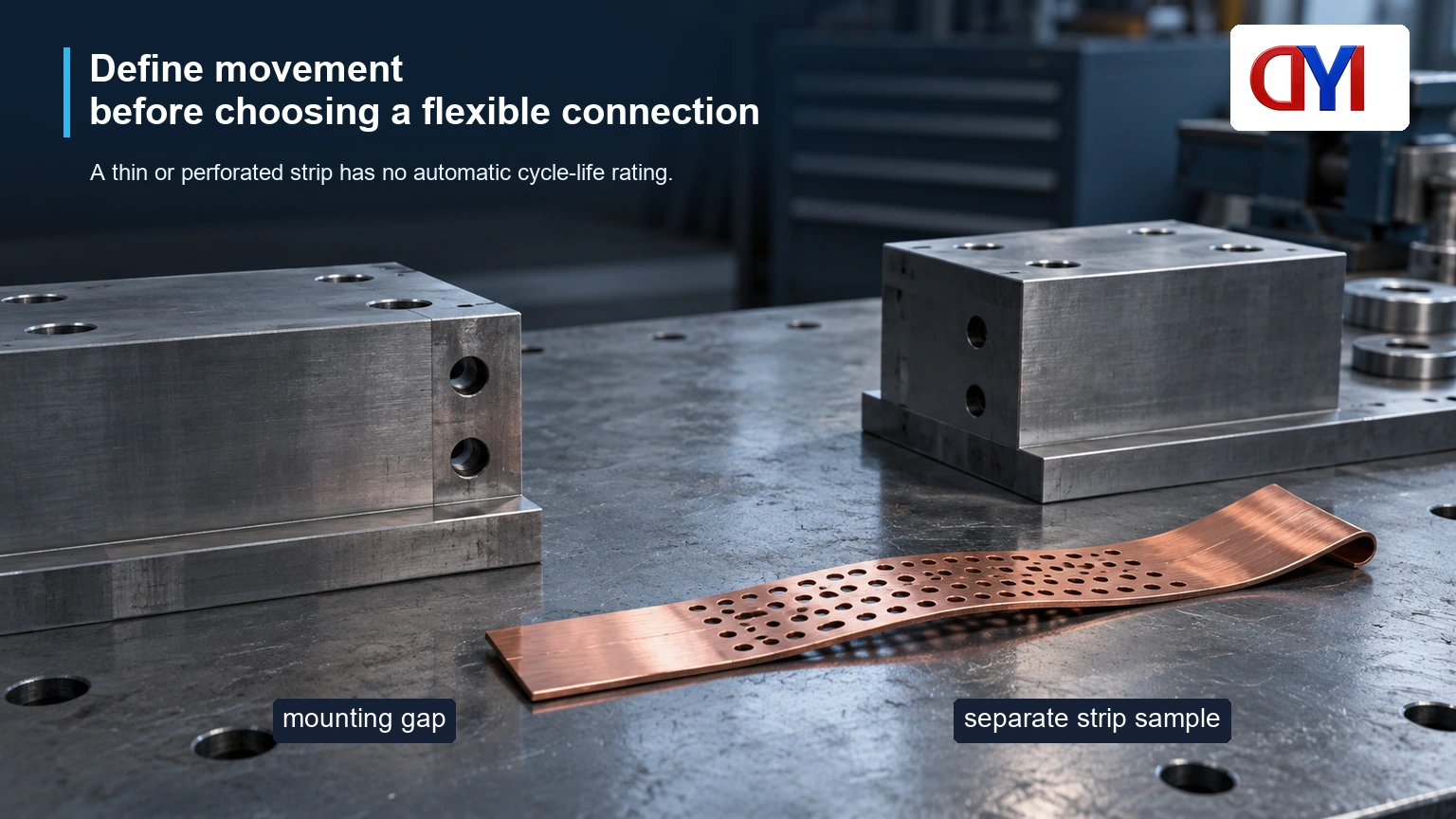
A rigid perforated strip can provide a defined mounting or connection geometry. Flexible copper connections may use a specifically engineered construction to accommodate movement or misalignment. “Copper strip soft connection” is a broad commercial phrase; ask what construction and duty it actually describes.
| Requirement | Rigid perforated strip | Flexible connection |
|---|---|---|
| Geometry | Fixed drawing and hole pattern | Defined end interfaces and free movement envelope |
| Movement | Must remain within the approved design | Direction, displacement and cycle duty specified |
| Section | Gross/net geometry must be assessed | Effective construction must be documented |
| Terminations | Approved fasteners and contact areas | Approved ends plus flexible-body attachment |
| Acceptance | Material, dimensions and assembly tests | Additional movement and endurance evidence as required |
Do not assume that bending a thin strip once proves repeated-flex capability. Specify movement direction, displacement, frequency or cycle count, temperature, installation envelope and current duty. These inputs define the qualification task; they are not a license to invent a cycle-life claim.
First-article checks and cost comparison
Inspect the first article against the controlled drawing, including hole locations, section, burrs, bends and surface condition. Check the assembled fit without forcing the part into place. Retain actual measurements and identify the drawing revision used.
For a flexible connection, verify the permitted movement and test construction separately from dimensional fit. A static continuity measurement cannot demonstrate fatigue life, and a movement trial without the electrical duty may not represent service. Agree on the applicable equipment requirements and qualification plan with the designer.
Compare tooling, setup, material yield, deburring, coating and inspection costs using actual quotations. A hypothetical saving of 1 unit per part over 500 accepted parts yields 500 units before tooling and qualification costs. The lower piece price may therefore be uneconomic for a short run or changing drawing.
RFQ and standards checklist
- Provide the current drawing with grade, temper and stock dimensions.
- Define holes, datums, burr limits and functional contact surfaces.
- Identify rigid or flexible service and the complete operating duty.
- Agree on first-article, lot-inspection and qualification evidence.
DONGYAO’s custom copper connector range can be reviewed for drawing-based fabrication. Its grounding strip assemblies illustrate another terminal arrangement, but do not establish the performance of a custom flexible shunt. Obtain written confirmation of the proposed construction and process.
ASTM material references and an electrical connection rule have distinct scopes. They do not by themselves certify a fabricated flexible connection. Apply the equipment and destination-market requirements relevant to the actual installation.
Frequently asked questions
What is a perforated metal sheet used for?
Applications include mounting, ventilation, screening and fabricated components. For copper connection parts, the hole pattern must follow the electrical and mechanical design. A generic perforated-sheet description does not establish suitability for carrying current.
How are hole size and pitch specified for perforated copper strip?
State hole diameter and tolerance, center positions or pitch, datum references and end distances. Identify slots and special features separately. Confirm which dimensions govern assembly acceptance.
Can copper strip be fabricated to a supplied hole-pattern drawing?
It may be possible using a suitable cutting, punching or drilling process. The supplier must review material, dimensions, tolerances and quantity. Approve the proposed process and first article before repeat production.
How can punching burrs affect an electrical connection?
Burrs can interfere with seating, damage adjacent insulation or alter stacking. Specify the allowed condition and deburring method. Inspect functional contact faces after processing.
When is a flexible copper connection preferable to a rigid perforated strip?
It may be appropriate where the design requires controlled movement, vibration accommodation or misalignment. The flexible construction must be qualified for that duty. A thin strip is not automatically an equivalent substitute.
What bend and continuity checks should be agreed for a custom flexible connection?
Define movement direction, displacement, cycle duty, installation geometry and electrical requirements. Agree on continuity or resistance measurements and any endurance testing required by the design. Keep static electrical checks separate from movement-life evidence.
References
- ASTM B187/B187M: copper bar and shape requirements
- ASTM B152/B152M: copper sheet and strip requirements
- ASTM B193-25: conductor resistivity measurement
- 29 CFR 1910.303: suitable electrical equipment and connections
Control the hole pattern for fit and the connection construction for duty. Contact DONGYAO with the drawing and movement requirements for a documented fabrication review.
For related conductor products, view the product categories.