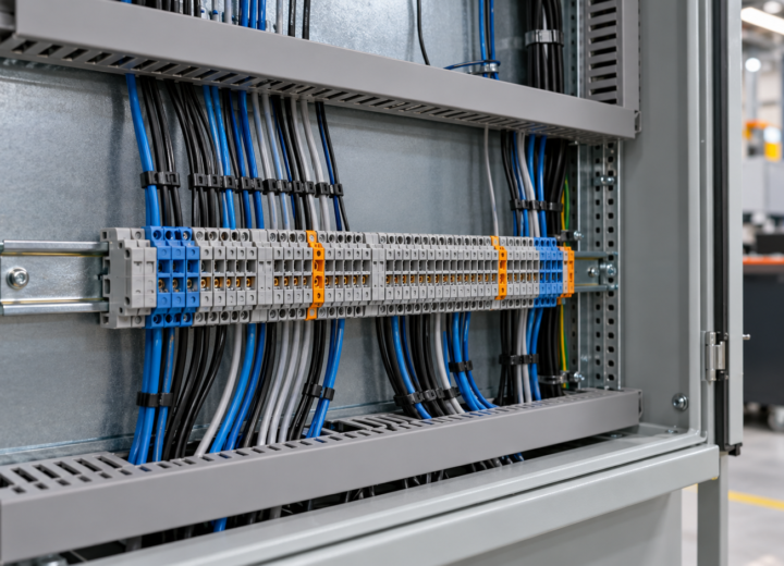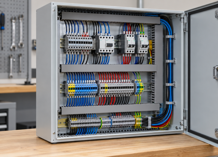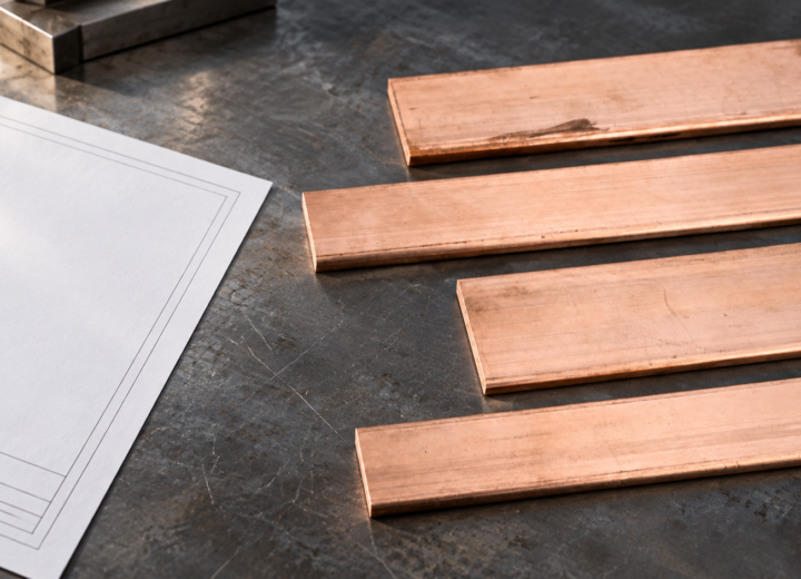
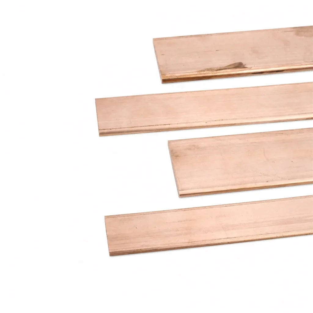
When a switchgear project engineer in Birmingham, Maya, encountered a late panel-fit problem, she released a revised connection drawing and watched the first trial assembly stop at the enclosure door: a bent bar cleared the terminals but its hole pattern no longer aligned with the mounting hardware. In this illustrative scenario, the visible failure appeared within minutes, yet the reversal was not “replace a bad bar.” The root cause was a specification that treated drilling, bending, and punching as separate purchasing details instead of one controlled geometry and assembly decision.
Summary: Drilled, bent, and punched copper bus bars should be specified from the assembly drawing outward: conductor section, interfaces, forming sequence, hole positions, and inspection points belong in the same release package. Copper’s commonly cited resistivity is approximately 1.68 × 10⁻⁸ Ω·m at 20 °C; that makes connection geometry and contact condition consequential, not cosmetic. For a CNC Drilling Copper Bus Bar, a Bent Copper Bus Bar, or a Punched Copper Bus Bar, request a drawing review before production and distinguish material specifications from assembly-level requirements.
CNC Drilling Copper Bus Bar work should start with the assembly drawing.
Drilling is often selected when a design calls for varied hole diameters, asymmetric patterns, or later engineering revisions. The useful question is not simply whether a hole can be made; it is whether its datum scheme, edge distance, mating hardware, and inspection reference remain clear after the bar is formed and installed. A drawing should identify the functional faces and the reference edges used by both fabrication and incoming inspection.
The electrical reason for that discipline is straightforward. The NIST reference data for copper places its resistivity near 1.68 × 10⁻⁸ Ω·m at 20 °C, while a practical connection also depends on its interfaces and assembled path. ASTM B193 is a test method for resistivity, not proof that a completed bar or panel will perform correctly in service.
For drawings with multiple interfaces, CNC Drilling Copper Bus Bar requirements are most useful when they state the finished-condition measurement logic. That avoids a costly loop in which a supplier verifies a flat blank, while the installer must judge a formed part against a different, unstated reference.
| Process | Best fit in a project | Drawing information that matters | Typical commercial trade-off |
|---|---|---|---|
| Drilling | Variable or revision-prone hole patterns | Datum faces, hole callouts, hardware stack-up | Flexible programming; review setup and inspection references |
| Bending | Routing around partitions, terminals, and clearances | Finished angle, bend direction, critical interfaces | Can reduce assembly pieces; requires form-aware checking |
| Punching | Repeated, defined patterns in stable designs | Pattern location, burr direction, mating hardware | Efficient repetition; late pattern changes deserve review |
Bent Copper Bus Bar geometry protects clearance, interfaces, and repeatability.
A formed bar can simplify a route that would otherwise need extra joints, spacers, or separate conductors. That potential value is real only when bend direction, terminal face, enclosure clearance, and installation order are considered together. The finished bar must be practical to position and fasten, not merely capable of existing in a 2D drawing.
For electrical context, the Copper Development Association’s electrical copper resource explains why copper is widely used for electrical applications. It does not remove the need to assess the full current path, including joints and terminations. Engineers should preserve the project’s own conductor-sizing basis and use it consistently when comparing a formed route with a multi-piece alternative.
Bent Copper Bus Bar reviews should also address the production sequence. A hole or slot that is convenient in the flat may become difficult to reference or access after forming; conversely, an early bend can change how the finished part is measured. This is a total-cost issue: resolving sequence before release is generally less disruptive than sorting rework, replacement parts, or installation delay after delivery.
Punched Copper Bus Bar features should be assessed as a process, not just a hole pattern.
Punching can be a sensible option for stable, recurring geometry, especially where the feature set is clearly controlled. Procurement teams should still ask what the drawing requires at the interface: hole size and location, burr direction where relevant, edge condition, and the relationship of each feature to the final mating surface. Those details help avoid ambiguity without asserting a tolerance or test result that the project has not specified.
The Copper Development Association’s standards and specifications guidance is a useful starting point for separating material terminology from a buyer’s fabrication and inspection requirements. In practice, a purchase order needs both: an agreed material/product-form basis and an unambiguous finished-part drawing. A named standard alone does not describe every feature of a custom fabricated bar.
Punched Copper Bus Bar decisions should therefore include the expected change rate. Repetition can support a streamlined process, while designs still undergoing terminal, enclosure, or hardware changes may benefit from a fabrication plan that makes revisions visible early. The illustrative ROI is simple: the right process is the one that lowers total engineering, inspection, assembly, and change-management effort—not merely the apparent piece cost.
| Application context | Feature priority | Useful drawing or procurement check | Decision risk if omitted |
|---|---|---|---|
| Switchgear or distribution assembly | Terminal alignment and clearance | Confirm finished orientation against the assembly layout | Fit-up issues at installation |
| Control-panel interconnection | Hole pattern and mounting sequence | Identify datums and hardware interfaces | Unclear inspection acceptance |
| Repeated equipment build | Repeatable feature set | Freeze the revision and revision-mark the drawing | Mixed configurations in supply |
| Export or multi-market project | Claim and documentation scope | Match requirements to destination and assembly use | Unsupported compliance language |
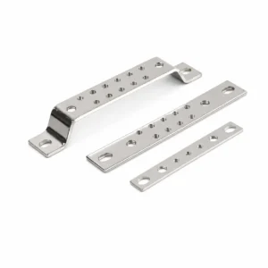
A selection guide for formed copper bus bars reduces late changes.
Put the finished condition at the center of the drawing package.
Show the installed orientation, relevant mating parts, connection faces, and the dimensions that govern fit. State whether a feature is measured before or after forming, then identify the datum system used for acceptance. This gives engineering, fabrication, and receiving teams one shared interpretation.
Separate material scope from assembly scope before making claims.
ASTM B187/B187M and ASTM B152/B152M are copper product-form and material specifications; they are not blanket approvals of a custom assembly. ASTM B193 is a resistivity test method. IEC 61439-1 concerns the assembly level, so it is not a certification for an isolated busbar; the IEC publication page should be read alongside the project’s applicable assembly requirements.
Align evidence with the destination market and intended use.
Compliance language should match what the buyer can substantiate for the destination market, intended use, and finished assembly. Unsupported claims can delay approvals, create contractual exposure, or cause a purchaser to expect documentation that was never part of the supply scope. Ask which drawings, material records, inspections, or assembly evidence are actually required before quotation.
Use supplier review to make change control visible.
Provide a controlled drawing revision, required quantity, interface hardware information, and any packing or identification needs. DONGYAO can support a drawing-led discussion of configurable copper bus bars and fabrication requirements; its service overview is a practical starting point for defining the information a quote should contain. Keep requested documentation and testing separate from claims that have not been verified for the final assembly.
Frequently asked questions about fabricated copper bus bars
What is the difference between drilling and punching a copper bus bar?
Both can create connection features, but they suit different production contexts. Drilling is often considered where patterns vary or require flexible programming; punching is often considered for repeated, stable geometry. The final choice should follow the finished drawing, material form, feature pattern, and change-control needs.
Should holes be specified before or after a copper bus bar is bent?
The drawing should state the finished-condition requirement and the datum system for acceptance. The fabrication sequence can then be selected with the supplier to protect access and measurement logic. Do not assume that a flat-pattern location alone communicates a formed-part interface.
Does ASTM B193 certify a copper bus bar?
No. ASTM B193 is a test method for electrical resistivity, rather than a certification of an isolated busbar or a finished electrical assembly. Use it only where its scope matches the requirement, and define any separate material, drawing, and assembly evidence needed for the project.
Does IEC 61439-1 apply to an individual bus bar?
IEC 61439-1 addresses low-voltage switchgear and controlgear assemblies at the assembly level. It should not be presented as a certification for an isolated busbar. Determine applicability from the finished assembly, destination-market requirements, and the claims made in sales or technical documentation.
What information should a procurement team send for a custom copper bus bar quote?
Send the controlled drawing, material/product-form requirement, quantity, revision status, relevant interfaces, and the documentation or inspection requests that are genuinely required. If the part will be bent or punched, include the finished orientation and any critical clearances. Clear inputs help suppliers respond to the actual project requirement rather than an assumed one.
References
- NIST, Physical Reference Data: Copper
- Copper Development Association, Electrical Copper
- Copper Development Association, Standards & Specifications
- International Electrotechnical Commission, IEC 61439-1 publication information
- International Copper Association, About Copper: material context and lifecycle information
Good busbar work is rarely decided by the last hole or the final bend; it is decided when the drawing makes every interface visible before metal is formed.
When your electrical project reaches that decision point, review the CNC Drilling Copper Bus Bar category and contact DONGYAO with the finished drawing, application context, and documentation needs.
For related conductor products, view the product categories.