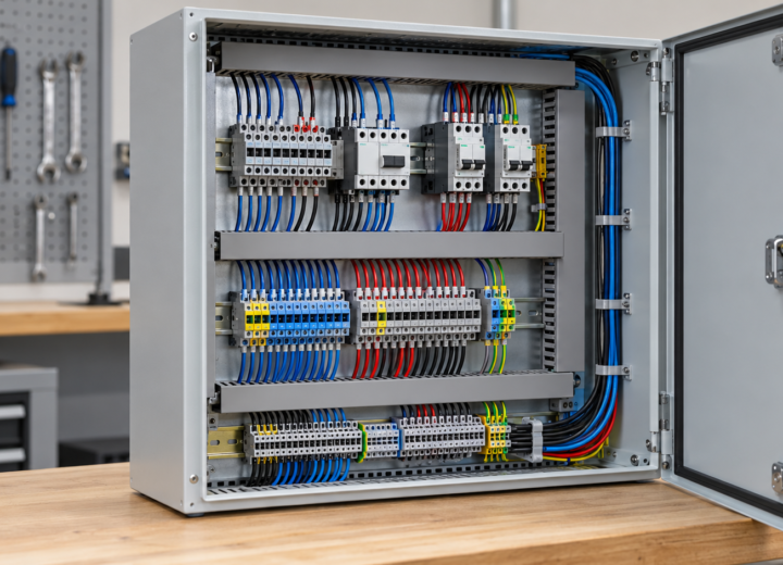
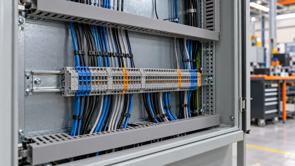
When Elena, a panel-builder in Brno, moved a terminal connector onto a crowded DIN rail, she tightened the screw, energized the cabinet, and saw a control fuse open within seconds. The selected wire range, bridge position, and strip length did not match the drawing; correcting the termination process restored the circuit.
How does a connector terminal block fit into a panel circuit?
A terminal block is an insulated body with a conductive clamp. It can join conductors, distribute a supply, bond PE, or add a fuse, disconnect, or test point. Select an interface that can be identified, inspected, and serviced without changing circuit intent.
Read the schematic and physical layout together. Mark the incoming conductor, outgoing load, protective device, shield or neutral function, and any bridge. A connector terminal block should have a stable reference such as X1:12 on the drawing and the same marker on both conductors. Separate circuit groups when the design calls for segregation.
Before wiring, check the rated conductor range, strip length, voltage, current, short-circuit context, temperature, and permitted accessories. A 2.5 mm² conductor that fits mechanically may still be outside the approved wire, ferrule, bridge, and end-stop combination. Use the exact datasheet; color or pitch alone is not a rating.
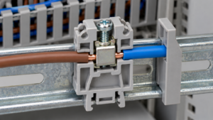
How should you install a DIN rail terminal block connector?
- Isolate the work. Identify every energy source, lock out where required, and prove the absence of voltage with a suitable instrument.
- Prepare the conductor. Cut squarely, strip to the stated length, and fit an approved ferrule only when the terminal instructions permit it. Do not leave loose strands or insulation under the clamp.
- Mount and bridge. Seat the block on the specified rail, install end stops and separators, and fit only the approved jumper or cross-connection. Verify polarity and circuit grouping against the drawing.
- Terminate and torque. Insert the conductor fully, tighten with the specified tool and torque, and record the method when the project requires traceability. Torque controls the joint; it does not create a higher current rating.
- Label and test. Mark both ends, perform continuity and polarity checks with power removed, then complete the functional or insulation tests required by the design.
After termination, inspect for exposed copper, damaged insulation, a displaced marker, an over-tightened screw, or a bridge touching the wrong circuit. Do not use a continuity beep as proof that the assembly is safe to energize.
Which terminal connector types suit common electrical panel tasks?
Function determines type. Feed-through blocks join conductors; multi-level blocks save width; PE blocks bond protective conductors; fused blocks hold a specified fuse; disconnect and test blocks support service work. A plug interface can speed removal, but mating and keying must be controlled.
| Type | Useful application | Control point | Total-cost tendency |
|---|---|---|---|
| Feed-through | Power or signal pass-through | Wire range, bridge, clearance | Low part cost; labor varies |
| PE/ground | Protective-conductor bonding | Rail bond and identification | Moderate; inspection is easier |
| Fused | Branch protection | Fuse type, interrupting duty, access | Higher hardware; simpler fault finding |
| Disconnect/test | Commissioning and measurement | Open indication and test procedure | Higher part cost; faster service |
| Multi-level | Dense I/O | Layer visibility, markers, probe access | Space saving; access is critical |
What dimensions should a connector terminal block drawing control?
Put the interface on the drawing before ordering. Rail width and pitch determine row length; wire range and strip length govern termination; height and depth affect clearance and access. State bridge pitch, end-stop and marker positions, separators, orientation, and cable bend radius.
| Dimension or feature | Why it matters | Evidence before release |
|---|---|---|
| Pitch, width, row length | Rail space and clearance | Layout and measured sample |
| Wire range, strip length | Clamp contact and insulation clearance | Datasheet and first-piece check |
| Height, depth, access | Duct, cover, tool and bend-radius fit | Enclosure fit check |
| Bridge and separator geometry | Prevents unintended commoning | Bridge schedule and continuity test |
| Marker and end-stop position | Readable identity and secure blocks | Photograph or inspection record |
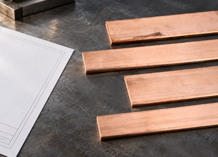
For conductive interfaces that connect a panel’s terminal row to a busbar or plate, review DONGYAO’s copper busbar terminals for cabinet assemblies. Keep the terminal drawing and the busbar drawing under the same revision so hole position, clearance, and hardware cannot drift apart.
How should buyers select a connector terminal block for repeatable builds?
Use this brief selection routine:
- Map circuit duty, conductor, environment, fault context, and maintenance task.
- Freeze block family, pitch, wire range, ferrule rule, bridge, separator, end stop, marker, and rail.
- Approve a sample and verify strip length, torque, retention, continuity, polarity, and access.
- Request current documents and retain required lot or change information.
DONGYAO supplies copper busbars, copper plates, brass plates, and electrical connection components for panel and OEM sourcing discussions. Send an approved drawing rather than a color or photo alone; for a custom interface, agree material, hole pattern, finish, tolerance, and inspection evidence before quotation. Related conductive interfaces are shown in the copper busbar category.
Frequently Asked Questions
What is the difference between a terminal block and a connector block?
A terminal block provides fixed screw, spring, or clamp terminations. A connector block may mean a removable plug interface or the same modular function. Confirm the drawing, mating parts, rating, and service method.
What are the different types of terminal blocks?
Common types include feed-through, PE/ground, fused, disconnect, test, multi-level, thermocouple, and sensor blocks. Select by conductor, duty, environment, segregation, and access; accessories can change the approved rating.
What are the different types of terminal block connectors?
They can use screw clamps, spring cages, push-in clamps, pluggable interfaces, or barrier terminals. The method affects preparation, vibration behavior, tooling, and inspection; verify current, voltage, temperature, and short-circuit conditions. Pluggable types also need controlled mating and keying.
How to use terminal block connector?
Isolate the panel, confirm the drawing and data, strip to length, insert the approved conductor or ferrule, torque, label both ends, and test before energizing. Recheck bridge position, exposed strands, polarity, and access; retain the approved sample and inspection record.
References
- NFPA 70, National Electrical Code.
- OSHA 29 CFR 1910.303, general electrical requirements.
- OSHA 29 CFR 1910.304, wiring design and protection.
Reliable terminal work is a chain: correct interface, controlled termination, verified circuit, documented change.
Need a drawing review or a conductive panel interface? Review the electrical connection component range and contact DONGYAO with the conductor schedule, terminal layout, dimensions, and destination-market requirements.
For related conductor products, view the product categories.