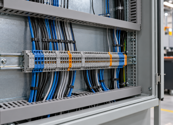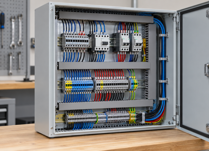
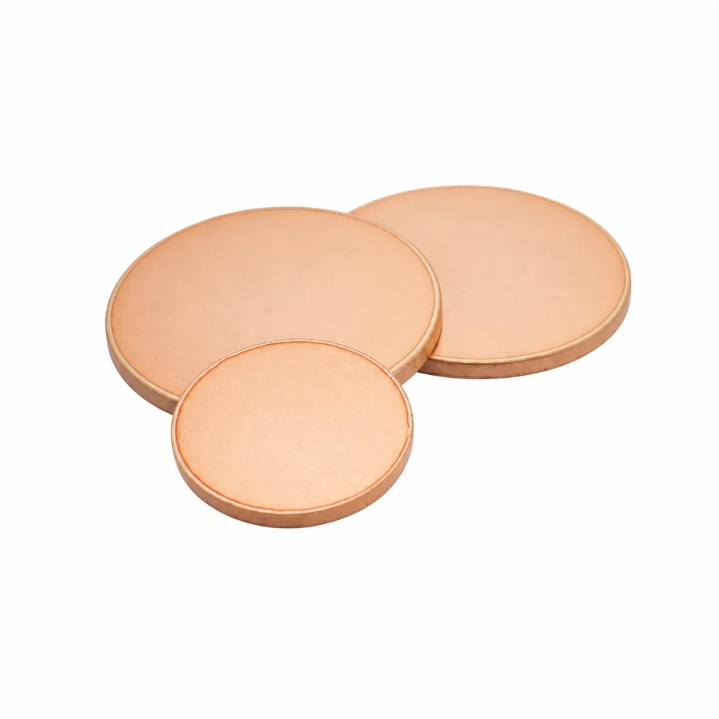
When a switchgear engineer in Manchester encountered intermittent heating at a revised cabinet connection, she replaced the suspect fitting and tightened the hardware again. The hot spot returned during review, and the drawing revealed the cause: the conductive path, contact area, and installation sequence had been changed independently. The issue was not simply a poor copper part; it was an incomplete custom-fitting specification.
Summary: Copper is widely used for electrical conductors, but conductivity alone does not establish the suitability of a fabricated connection. ASTM material specifications and IEC 61439-1 address different questions: one concerns material forms, while the other sets assembly-level general rules. Define current path, interfaces, geometry, and verification responsibility before ordering a fitting.
Custom copper fittings transfer conductivity through defined material and joint interfaces
The question “is copper conductive?” has a straightforward material answer, but the engineering answer is broader. Copper carries electrical current efficiently, which is why it appears in busbars, terminals, grounding parts, and formed connectors. In equipment, however, the useful path includes every mating surface, fastener stack, bend, and interface between the source and the connected device. Asking is copper conductive is therefore only the first screening question.
Copper Conductivity is commonly discussed through material properties, yet a fabricated part should never be judged on a material value alone. For screening purposes, Copper Conductivity helps explain material selection, but it does not settle the joint design. A small contact area, an incompatible surface condition, or inaccessible tightening process can govern a connection long before the bulk copper section becomes the central concern. The assembly design must therefore define how the part is installed and verified.
For purchasing and traceability, ASTM B187/B187M provides a material-reference scope for copper bus bar, rod, and shapes. That reference can help identify a supply form, but it does not prescribe the finished fitting’s current rating, temperature rise, or short-circuit performance. Those outcomes depend on the actual arrangement, declared duty, enclosure, joints, and assembly verification.
A practical first review traces the current path in both directions. Record the device pad, mating conductor, mounting hardware, contact faces, and required tool access. This makes the drawing answer a more useful question than whether copper is conductive: whether the intended conductive path can be built consistently and inspected after other cabinet components are in place.
Custom copper fittings require geometry that preserves the intended current path
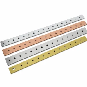
A fitting may be flat, offset, bent, drilled, threaded, or shaped to clear a barrier or reach an equipment terminal. Each feature changes the fabrication and inspection task. The drawing should establish datums, finished dimensions, hole diameters and centres, bend locations, edge condition, and handedness where a mirrored part could be installed incorrectly.
Material thickness and width are necessary inputs, but they are not a complete definition. The designer should distinguish a fastening hole from the actual contact region, identify surfaces that must remain flat, and show which areas may be plated or masked. A formed part can fit nominally yet create an unsuitable joint if the available overlap or wrench access differs from the design intent.
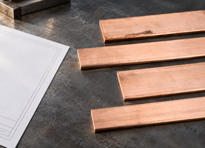
Where the starting material is a flat product, copper plate options can frame the sourcing discussion, while the final fitting remains a drawing-controlled fabricated component. ASTM B152/B152M is relevant to copper sheet, strip, plate, and rolled bar; it is a material specification, not a certification of a finished electrical assembly or a universal indication of service performance.
Dimensional inspection against the released revision is a direct way to check whether the fabricated shape matches the purchase requirement. Depending on the feature, an inspection plan may include hole-position measurement, bend-angle confirmation, visual review of edges, or a first-article fit-up. These checks demonstrate conformance to stated geometry; they do not replace the system engineering required for electrical duty. They also answer whether is copper conductive is the relevant issue, rather than a question of fit or contact control.
Custom copper fittings should be compared by installed cost rather than copper content alone
Two fittings made from similar material can create markedly different installation effort. A simple flat connector may suit a stable interface, whereas a formed fitting can eliminate adapters and field drilling in a constrained enclosure. The appropriate comparison includes drawing maturity, mounting access, inspection effort, revision risk, and the consequence of discovering a mismatch after devices and barriers are installed.
| Decision factor | Stock material adapted in the panel shop | Drawing-based custom fitting |
|---|---|---|
| Geometry control | May depend on local cutting, drilling, and forming. | Can be defined by a revision-controlled drawing. |
| Interface fit | Requires checking after adaptation. | Can be reviewed against known mating faces before release. |
| Unit-cost tendency | May be simpler for basic straight pieces. | Depends on features, quantity, material, and finishing. |
| Installation labor | Can include local preparation and deburring. | Can shift defined fabrication upstream. |
| Change visibility | Can be difficult if changes occur at fit-up. | Can be tracked through drawing revisions. |
An illustrative total-cost calculation would add the quoted component, receiving checks, panel-shop preparation, installation time, and the likely cost of rework if a critical interface is unclear. It should not assume that custom work is always the lower-cost route. Its purpose is to compare the whole installation decision before a price-only selection makes late modification more likely.
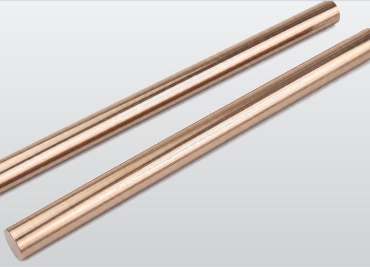
The form of the input material also affects procurement conversations. For straight or machined starting sections, copper rod supply forms may be relevant, but a fitting’s fitness still rests on its approved geometry and mating requirements. Treat the raw material and the installed component as related yet separate items in the specification.
Custom copper fittings change specification priorities across electrical applications
Application context turns a generic copper fitting into an actionable design request. A distribution cabinet, a renewable-energy enclosure, and an OEM replacement each have different device interfaces, routing limits, service expectations, and documentation needs. The table below organizes those differences as questions for the design and purchasing teams; it does not assign any universal current capacity or performance classification.
| Application context | Drawing questions to resolve | Useful evidence |
|---|---|---|
| Low-voltage cabinet distribution | Can the fitting be mounted, tightened, and inspected with barriers in place? | General arrangement, interface drawing, and assembly sequence. |
| Grounding or bonding connection | What is the protective function, mating hardware, and marking requirement? | Project grounding design and controlled hole pattern. |
| Equipment retrofit | Which existing pads, offsets, and clearances must remain compatible? | Site measurement, drawing revision, and sample fit-up. |
| Repeat OEM build | Which features must be identical across scheduled units? | Approved revision, inspection requirement, and order reference. |
Design teams should separate conductive duty from mechanical convenience. A bend that improves routing can alter access to a bolted joint; a hole relocation that helps one device can change clearance at another. Copper Conductivity remains a material consideration, but it cannot replace that interface review. Reviewing the fitting in its installed orientation, with adjacent hardware represented, is more reliable than approving an isolated outline without the surrounding assembly context.
Custom copper fittings must be described without overstating compliance
IEC 61439-1 provides general rules for low-voltage switchgear and controlgear assemblies. It helps frame the assembly-level design-verification conversation, but it does not certify an individual loose fitting. IEC requirements, where applicable, must be interpreted for the actual completed assembly, its declared characteristics, and the party responsible for verification.
In the United States, OSHA 29 CFR 1910.303 contains general requirements for electrical equipment in its regulatory context. Its applicability depends on the workplace and jurisdiction; it is not a product label for a copper component. NEMA industrial-control standards also have defined scopes, so a supplier should not use a standard name as unsupported proof that a custom fitting meets every installation requirement.
IEEE 3001.2 is a recommended practice related to evaluating electrical service requirements. It does not supply a universal bolt torque, fitting dimension, or acceptance test for every conductive component. A credible submittal instead separates material references, dimensional inspection, manufacturer installation instructions, and the system-level verification evidence that genuinely applies to the delivered equipment.
Unsupported claims create commercial risk because they can blur the boundary between a supplied part and a verified assembly. Copper Conductivity claims should be tied to the material evidence actually supplied, while installed-performance claims require the applicable assembly context. Specify the destination market, intended use, drawing revision, requested inspection records, and responsible verification route. If a project requires a particular test, the request should name the method, specimen, conditions, acceptance criteria, and report expectation before production is authorized.
Custom copper fittings are selected most reliably through a controlled procurement package
First, release a single controlled drawing and identify the electrical contact faces, rather than relying on a generic product name. Second, record mating hardware, adjacent clearances, tool direction, and the mounting sequence. Third, establish the assembly performance basis and acceptance package before quotations are compared. These steps preserve the information that determines whether a conductive part can be installed as intended.
Fourth, request that any changes in material form, finish, dimensions, or fabrication method be returned to the drawing owner for review. Fifth, use a sample or first-article dimensional check when the connection is new, constrained, or repeat-critical. These procurement controls cost less than discovering that a revised fitting conflicts with installed equipment or cannot be reached with the specified tool.
For projects that require drawing-based conductive parts, Dongyao can be considered as a sourcing partner for Custom Copper Fittings and related copper components. The useful starting point is a clear interface package, because it lets the supplier, buyer, and assembly engineer discuss the same geometry, finishing needs, and inspection expectations without implying unverified assembly performance.
Frequently Asked Questions clarify custom copper fitting decisions
Is copper conductive enough for every electrical fitting?
Copper is a widely used electrical conductor, but material conductivity alone does not establish that every fitting is suitable. The installed connection also depends on section, joint geometry, surface condition, mounting hardware, operating duty, and the finished assembly. Confirm the complete interface and verification basis instead of selecting only by material name.
What should a Custom Copper Fittings drawing include?
Include material and finish requirements where specified, overall dimensions, thickness, width, holes, bends, datums, contact faces, handedness, and revision status. Also describe mating components, hardware access, and inspection expectations. This lets a supplier manufacture to a controlled requirement while the assembly owner retains responsibility for system performance.
Does a copper material standard provide an electrical current rating?
No. A material specification can define the scope of a copper product form, but it does not establish a universal current rating for a finished fitting. Installed performance depends on the equipment configuration and declared operating conditions. Use the applicable assembly engineering and verification route for the actual design.
How should a formed copper fitting be checked before ordering?
Review it against the mating pads, enclosure boundaries, adjacent conductors, barriers, and the actual tool path for fastening. Then confirm holes, bends, contact faces, and datum references on the released drawing. A first-article dimensional inspection or fit-up can be appropriate when the geometry is new or the available clearance is limited.
Can a supplier claim IEC 61439 compliance for a loose copper part?
Not as a stand-alone conclusion. IEC 61439-1 addresses low-voltage switchgear and controlgear assemblies, so the claim needs an identified assembly scope and verification responsibility. A component supplier can provide agreed material or dimensional documentation, while the organization responsible for the finished assembly evaluates the applicable requirements.
References:
Copper Development Association: Electrical Busbars
IEC 61439-1
OSHA 29 CFR 1910.303
NEMA Industrial Control and Systems
IEEE 3001.2
Specify the complete interface before comparing the copper part; conductivity becomes useful only when the finished path can be installed and verified as designed.
When the drawing and assembly references are ready, contact Dongyao through a focused project discussion to align the custom fitting request with the intended equipment.
For related conductor products, view the product categories.