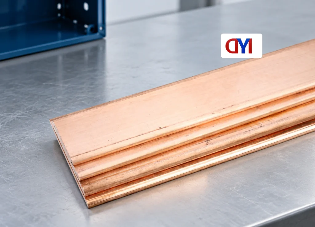
Illustrative scenario: When a panel buyer in Leeds checked a newly delivered copper strip, the specified lugs did not fit the drilled pattern and the enclosure bond was undefined. A continuous-load table could not resolve either issue. The missing inputs were the protective function, connection schedule and fault-duty evidence.
Summary: A grounding bar provides a common termination and bonding point for protective conductors. It supports equipotential bonding and the designed fault-return path; it normally does not carry load current. A 40 mm × 5 mm strip has a gross cross-section of 200 mm², but that geometry alone establishes no current rating. Specify the system function, connections, fault duty, and destination requirements before choosing dimensions.
OSHA 1910.304 requires an effective, permanent, continuous ground path within its US workplace scope. Assess the bar within that system, rather than by appearance.
A grounding bar is a common protective connection point
A grounding bar collects protective connections from frames, cabinets, and designated metalwork. It helps maintain a common potential and the designed fault-current path. It is a function-specific busbar; phase and neutral busbars normally serve load-current circuits.
OSHA 1910.399 defines bonding through permanent metallic joining, continuity, and capacity for the imposed current. A grounding electrode instead contacts earth. Earth alone must not be assumed to clear a fault; earthing arrangements, protective devices, and fault loops require coordinated design.
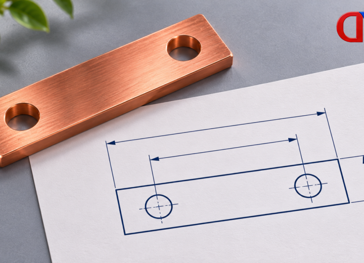
A drawing for a grounding bar should state its protective function and hole layout. Identical strips may have different uses. Neutral-to-protective separation and the authorized bonding location depend on the system and local rules.
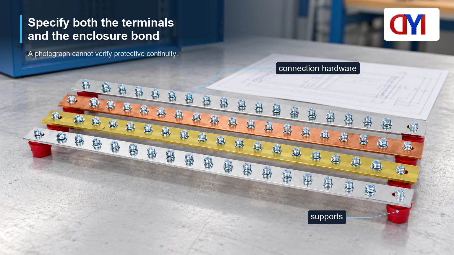
Specify both the terminals and the enclosure bond
A grounding bus bar needs specified connections: conductor material and size, terminal type, hardware, and manufacturer instructions. One or two conductors cannot be assigned by appearance: OSHA 1910.303 requires terminals for more than one conductor to be identified for that use.
Mounting hardware needs equal attention. Insulating supports can position a strip mechanically without bonding it to the cabinet. The design must establish the required bonding conductor or other documented conductive path; mounting screws should not be presumed to provide it. Red supports and a silver finish identify neither electrical function nor certification.
Request a drawing showing the bar, supports, connections, and enclosure interface. Physical inspection requires isolated, safely controlled conditions, qualified personnel, and applicable procedures. A photograph cannot verify protective continuity.
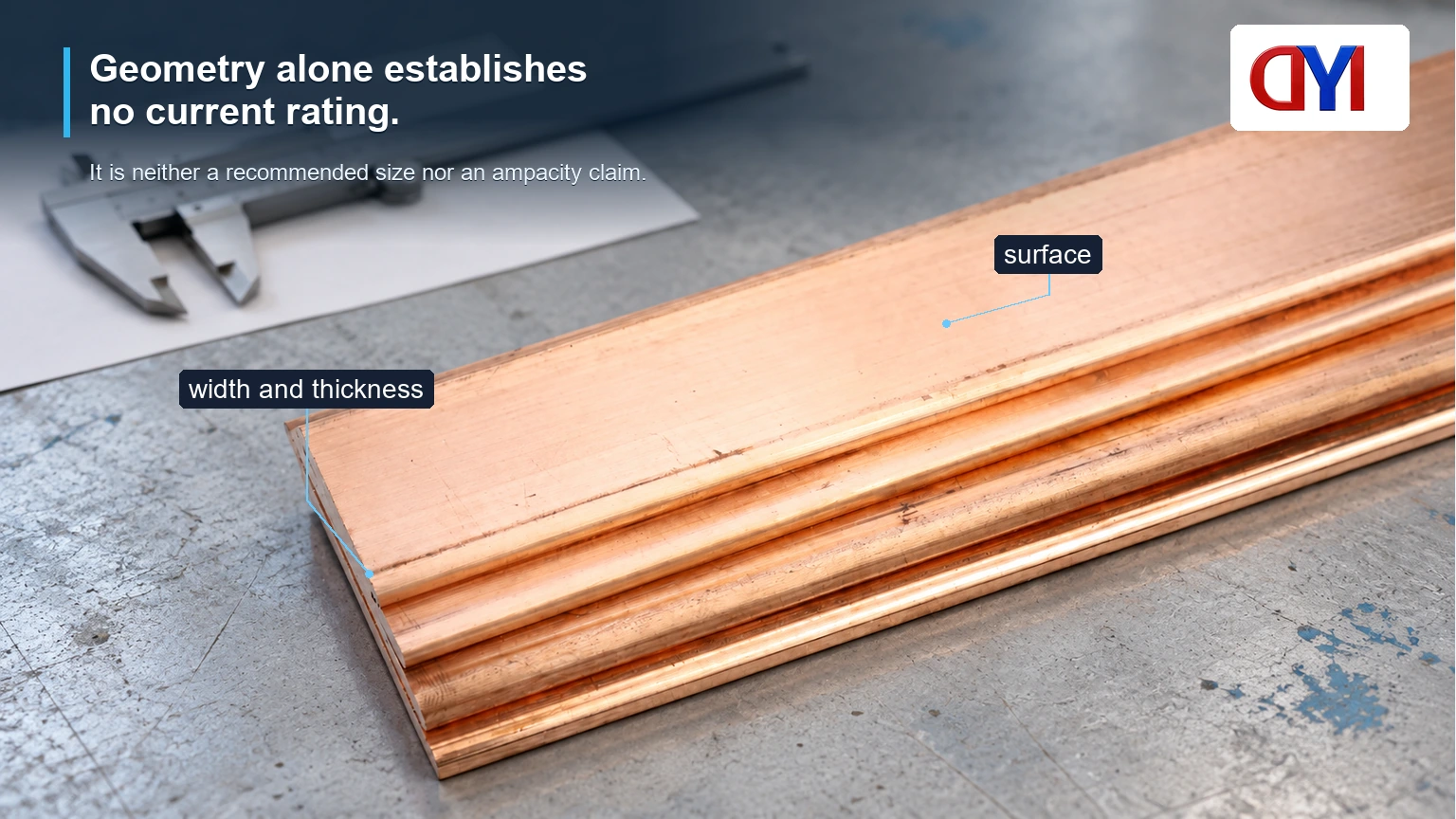
Size for the protective duty and complete assembly
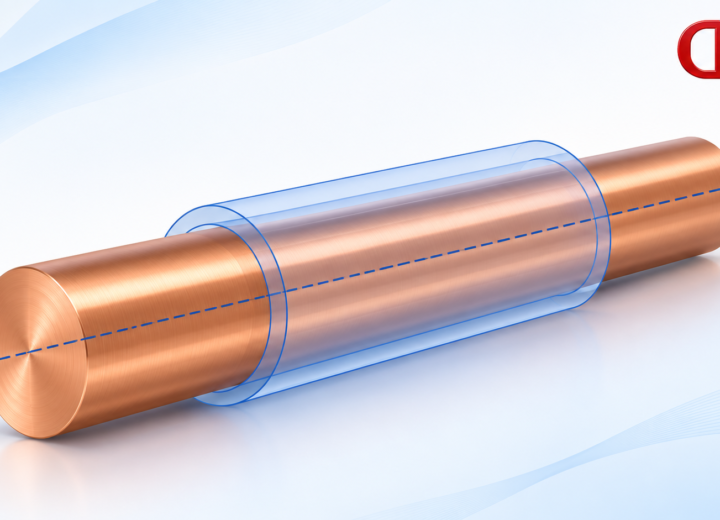
A copper grounding bar specification needs more than width and thickness. The 40 mm × 5 mm example gives 200 mm² of gross metal area only; drilled holes, net sections, connection zones, and mechanical support must be checked separately. It is neither a recommended size nor an ampacity claim.
Specify prospective fault current, protective-device clearing time, material and temperature limits, environment, and the assembly’s documented rating or verification basis. Supports and connections require suitable thermal and mechanical duty. Phase-busbar continuous-current tables do not establish protective-conductor fault capability.
OSHA 1910.303 addresses conductor-material suitability and the use of identified connections for dissimilar metals. State both the bar material and conductor material: bare copper, plated copper, and brass are distinct purchasing choices. Finishes may suit a specified interface or environment, but plating alone does not establish connection compatibility or service life.
Compare material and finish against the same connection duty
Compare the same drawing and connections. Incompatible terminals, extra machining, or missing assembly records can outweigh a lower strip price.
| Choice | What to verify | Cost or maintenance implication |
|---|---|---|
| Bare copper | Material specification, contact arrangement, exposure | Finish preparation and interface maintenance depend on service conditions. |
| Tin-plated copper | Base material, finish specification, terminal compatibility | Plating adds a process; compare complete connection requirements. |
| Brass or plated brass | Material properties and suitability for the required duty | Do not substitute solely because dimensions match. |
For tin-plated terminal bars, confirm the drawing’s neutral or protective designation. A shared product format does not make those functions interchangeable. OSHA 1910.303 also requires suitability for the operating environment, so the quotation should describe exposure conditions rather than assume every finish is adequate.
Translate the application into drawing inputs
| Application | Drawing input | Likely cost driver |
|---|---|---|
| Rack cabinet | Mounting span, access space, terminal positions | Support arrangement and hole pattern |
| Control enclosure | Conductor schedule, enclosure bond, terminal identification | Connection hardware and assembly documentation |
| Custom distribution assembly | Fault duty, cross-section, bends, support spacing | Material volume, forming, finish, and verification |
Separate gross bar area in mm² from code-selected conductor sizes. Reserve positions need usable access and identified terminals, not just spare holes. Record these details through drawing-based customization to obtain comparable quotations and reduce changes after delivery.
Check the destination requirements and evidence scope
OSHA 1910.304(g)(5) addresses the effectiveness and continuity of ground paths in covered US workplaces. OSHA 1910.303(b)(2) requires listed or labeled equipment to follow the instructions included with its listing or labeling; its connection provisions address suitable conductor materials and identified terminal uses. OSHA 1910.399 supplies relevant definitions.
These sources neither set universal strip dimensions nor certify a supplier’s product. Installation codes, assembly standards, and required evidence depend on destination, use, and earthing arrangement. TN, TT, and IT systems have different fault-protection requirements.
Have the responsible engineer identify required documentation before ordering. Unsupported ratings or certification claims risk rejected submittals, redesign, and delayed acceptance.
Keep the protective grounding bar and neutral-bar designation explicit on the drawing and parts list. A strip on insulating supports may be useful mechanically, but that appearance says nothing about its intended electrical function or enclosure bond. Show the approved bonding interface and leave the permitted neutral-to-protective connection location to the installation design and applicable rules. A material certificate cannot replace evidence for that completed path.
Resolve the purchasing specification before comparing prices
- Define the function. Record protective bonding, system arrangement, destination requirements, and the intended enclosure interface.
- Freeze the connection schedule. List conductor materials and sizes, identified terminals, usable positions, and manufacturer instructions.
- Confirm the duty. Obtain engineer-approved sizing and the required assembly evidence for fault current, clearing time, environment, and supports.
- Approve the drawing and scope. Check dimensions, holes, bends, finish, hardware, and supplied documentation before comparing quotations.
DONGYAO, Wenzhou Dongyao Trading Co., Ltd., offers configurable dimensions, hole layouts, bends, and finishes. Send a controlled drawing and connection schedule; confirm the required finished-assembly evidence separately.
Frequently asked questions
What is the difference between a grounding bar and a bus bar?
The former is a busbar assigned to protective grounding or bonding. Other busbars distribute phase or neutral current, so similar construction does not establish equivalent duty or permit swapping their functions.
What is a grounding bus bar?
It is a common conductive termination point for protective connections. Its effectiveness depends on the complete designed path, including terminals, bonding connections, and coordinated fault protection.
Can you use copper for grounding?
Yes, copper is used for protective conductors and bars when suitable for the design. A copper grounding bar still requires compatible connections, appropriate dimensions, and evidence for its environment and duty.
How to size a grounding busbar?
Start with the applicable code and assembly requirements, prospective fault current, clearing time, and material limits. Have the responsible engineer assess the bar, connections, holes, and supports together; there is no universal size or continuous-current shortcut.
References
- 29 CFR 1910.304: Wiring design and protection (Cornell LII text) — ground-path requirements within its stated scope.
- 29 CFR 1910.303: General requirements (Cornell LII text) — equipment instructions, connections, and environmental suitability.
- 29 CFR 1910.399: Definitions (Cornell LII text) — bonding, grounding, and associated conductor terminology.
Specify the protective path first; choose the metal strip within that design.
Review DONGYAO’s cabinet grounding strips and contact the team with your drawing, material designation, terminal schedule, and documentation requirements for a configuration-specific quotation.
For related conductor products, view the product categories.