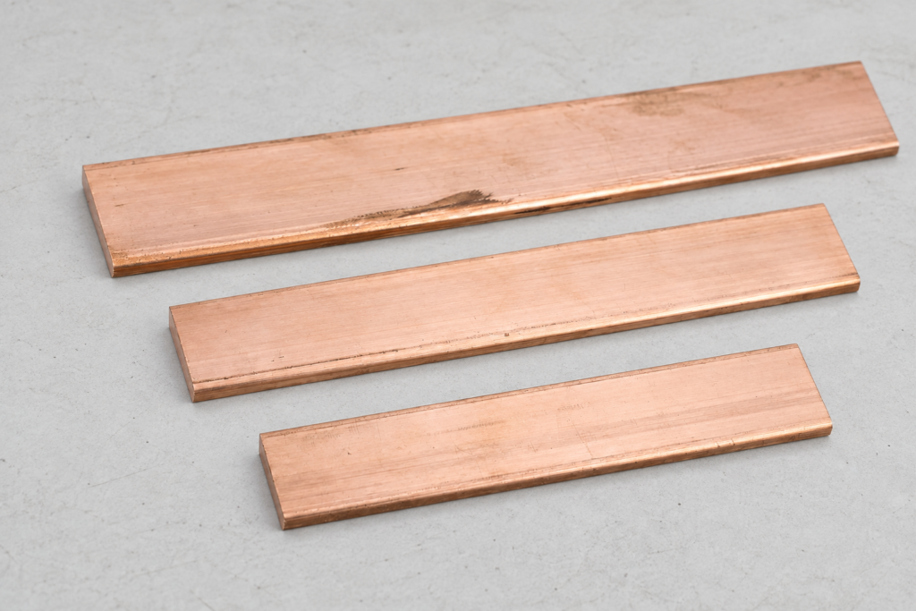
When a commissioning engineer in Suzhou encountered a failed continuity reading during a panel check, she tightened the visible fastener and repeated the test. The reading still fluctuated as the enclosure door moved. The cause was not simply a “bad” component: the bracket had a painted contact surface, unsuitable hardware, and no defined path to the earth bar. Once the interface and bonding route were specified together, continuity became stable.
What a Grounding bracket does in the fault-current path?
The purpose of a Grounding bracket is to maintain an intentional conductive connection between a metal part and the protective-earth or equipotential-bonding network. In a typical enclosure, the bracket may join a door, removable cover, mounting plate, cable tray, or frame to a nearby earth point. It is not the same thing as a decorative support, a signal reference, or a ground electrode; its job is to keep exposed conductive parts at a controlled potential and to help fault current reach the protective device through the designed path.
A bonding path consists of the metal part, bracket, mating surfaces, fastener stack, bonding conductor or copper link, and an earth bar or local grounding bar. Each interface adds contact resistance and can add inductive impedance during a fast transient. For fault protection, the complete path must carry prospective fault current long enough for the protective device to operate; a bracket cannot compensate for an undersized conductor or interrupted bonding design.
How a grounding bar connects equipment to a grounding busbar?
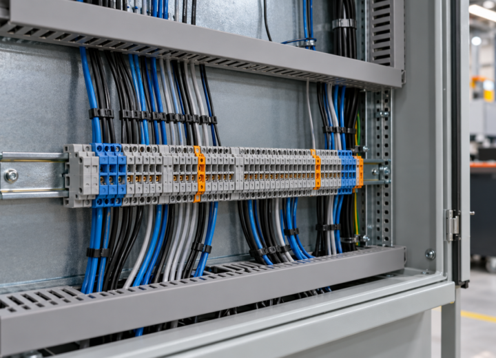
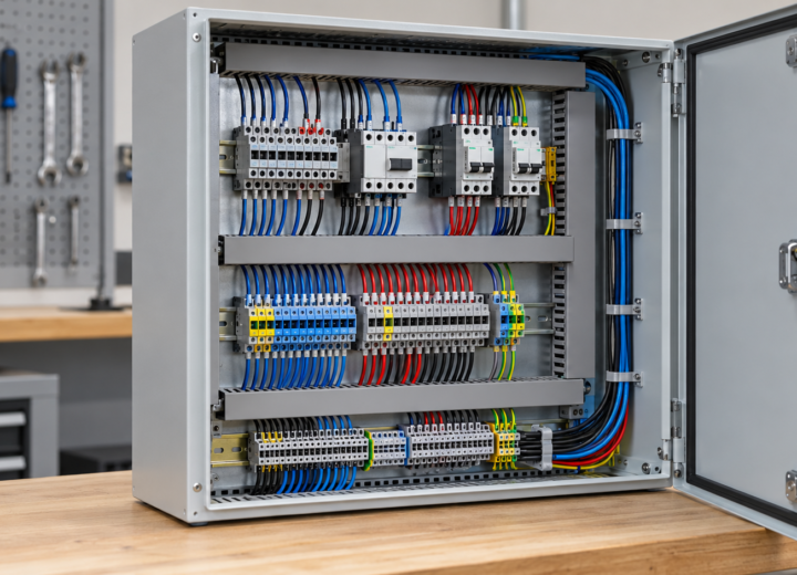
In an electrical cabinet, the local grounding bar collects protective conductors and bonding links; it may then connect to a main earthing terminal or a larger grounding busbar. A bracket is the interface that makes a removable metal section part of that same network. The design should show where the bracket lands, which surfaces are electrically prepared, how the conductor terminates, and how the path remains intact when the equipment is serviced; verify it with the specified continuity test after final assembly.
Mechanical and electrical interfaces have different but overlapping requirements. Mechanically, the bracket needs adequate bearing area, stable clamping, suitable hole clearance, and resistance to loosening from vibration or door movement. Electrically, the joint needs clean conductive contact, a reliable fastener stack, compatible metals, and a path that does not depend on paint, thread sealant, a hinge pin, or a loose washer. If a painted enclosure must be bonded, define whether the coating is removed locally, whether a listed bonding washer or serrated interface is allowed, and how the exposed area will be protected afterward.
How to install and inspect a grounding bracket in a grounding bar assembly?
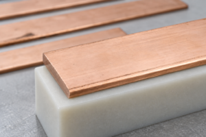
A practical grounding bracket installation plan starts with the drawing rather than the hardware bin. Identify every exposed conductive part that needs bonding, the destination grounding bar or grounding busbar, conductor routing, access constraints, and the inspection hold point. Then verify the bracket’s hole pattern, contact footprint, material, finish, fastener compatibility, and any required conductor lug before production.
- Prepare: confirm the approved bonding route and isolate the joint from paint, burrs, sealants, and contamination only as permitted by the design.
- Assemble: use the specified hardware order and torque; keep the conductor lug flat, supported, and free from bending stress at the termination.
- Protect: seal or coat exposed areas with a compatible method, while keeping the conductive contact and inspection features accessible.
- Verify: perform the specified continuity or low-resistance test from the bonded part to the grounding bar or grounding busbar, and document the result.
- Recheck: repeat the inspection after door movement, final cable work, or any operation that could disturb the joint.
Inspection should look for more than a present fastener: check the grounding bracket, contact preparation, washer and lug seating, torque evidence, routing, corrosion protection, labels, and continuity records. If results vary, isolate loose hardware, coating under the contact, a broken conductor, parallel paths, instrument error, or an unvalidated design assumption. A passing number without a traceable test point is weak evidence.
| Approach | Mechanical interface | Electrical implication | Durability and maintenance | Best-fit use |
|---|---|---|---|---|
| Dedicated copper or plated copper bracket | Broad, defined contact area with specified hardware | Direct low-impedance bond when surfaces and conductor are coordinated | Requires finish and galvanic-compatibility review | Enclosures, frames, and fabricated assemblies with a documented bond |
| Bonding strap or flexible link | Accommodates movement or removable covers | Maintains a separate path when hinges are not relied upon | Inspect for fatigue, looseness, and routing damage | Doors, covers, vibration, and service access |
| Paint-piercing or serrated interface | Designed to break through a defined coating at clamping | Can reduce preparation work only when approved for the assembly | Needs corrosion-control and torque discipline | Coated enclosures where the hardware system is specified |
| Ad hoc bolt, washer, or hinge path | Geometry varies and contact may be accidental | Continuity can be intermittent or difficult to prove | High inspection and rework risk | Not a preferred protective-bonding strategy |
| Dimension | Question for engineering | Evidence for procurement and inspection |
|---|---|---|
| Electrical duty | What fault, protective-device, and bonding requirements govern the path? | Single-line or bonding drawing, conductor schedule, and test criterion |
| Mechanical movement | Will a door, cover, tray, or frame move or be removed? | Movement allowance, flexible link requirement, and service instruction |
| Environment | Will moisture, salt, chemicals, heat, or vibration affect the joint? | Material/finish decision and corrosion-control instruction |
| Manufacturing repeatability | Can operators prepare, torque, protect, and test the joint consistently? | Work instruction, torque record, inspection point, and traceable result |
| Documentation | What must be supplied with the assembly? | Drawing, material data, applicable test report, and installation record |
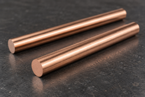
Fastener seating, finish transition, and corrosion protection during final inspection.
Frequently Asked Questions
What is a grounding busbar?
A grounding busbar is a conductive bar or assembly point that collects protective-earth, bonding, or equipment-grounding conductors and connects them to the defined earthing system. Its size, material, mounting, and separation requirements depend on the installation and applicable rules.
What does a grounding busbar do?
It provides a common, organized termination point for bonding conductors and helps create a deliberate low-impedance route from exposed conductive parts toward the earthing system. The bar alone does not guarantee safety: brackets, lugs, fasteners, conductors, and upstream connections must all be continuous and appropriately designed.
What is a main earth busbar?
A main earth busbar is the principal bar or terminal arrangement where protective conductors, bonding conductors, and sometimes functional earthing connections are coordinated for an installation. Terminology varies by region and system design, so the project drawings and local rules govern the exact role. Confirm whether neutral, functional earth, lightning protection, or other services must be separated or connected under the design.
Where are grounding busbars used?
They are used in switchboards, control panels, industrial enclosures, building electrical rooms, equipment frames, and cable-management systems that require organized protective bonding. Select the bracket and conductor route for the actual environment and service movement, not merely the enclosure label.
References
- IEC 60364-5-54: Low-voltage electrical installations—earthing arrangements and protective conductors
- NFPA 70: National Electrical Code
- UL 467: Grounding and Bonding Equipment
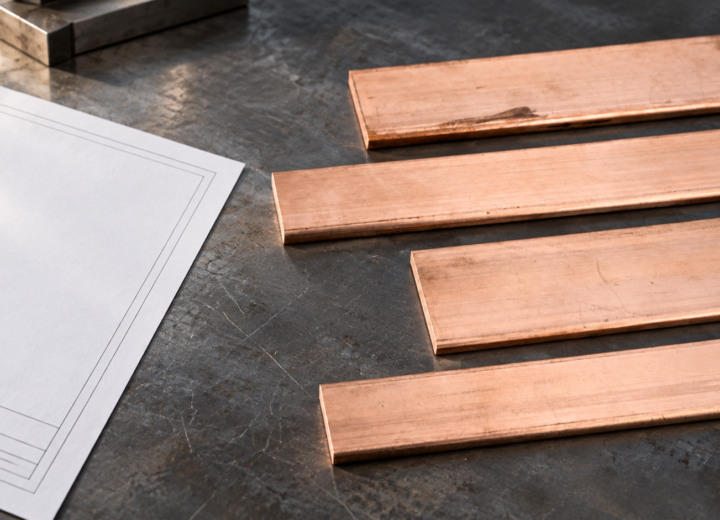
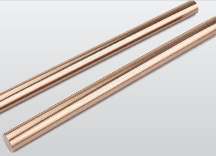
For help matching a drawing to a manufacturable copper or metal interface, review the copper plate and connection material options, then contact DONGYAO with the assembly drawing, environment, and inspection requirement.
For related conductor products, view the product categories.