A dimension line indicates the direction and extent of a dimension on an engineering drawing. Its arrows identify the limits being dimensioned, while the associated text gives the value. Read the line, its referenced geometry and the drawing’s units together; the line’s appearance alone is not a complete size requirement.
Dimension lines belong to a group of annotations with different jobs. An extension line identifies where a dimension refers to the part. A leader connects a note to a feature. Confusing those jobs can turn an overall length into a hole-location assumption.
Dimension line, extension line and leader: recognize the job
Follow the connection to the part before interpreting the text. The introductory distinctions below apply to the common examples shown here; the drawing’s specified standard and annotation style control its detailed presentation.
| Element | What it communicates | What to trace |
|---|---|---|
| Dimension line | The direction and span of the dimension | Its ends and associated value |
| Extension lines | The points or features to which the dimension refers | Back toward the relevant edges or feature locations |
| Leader | The feature to which an annotation applies | From the note along the leader to its arrow |
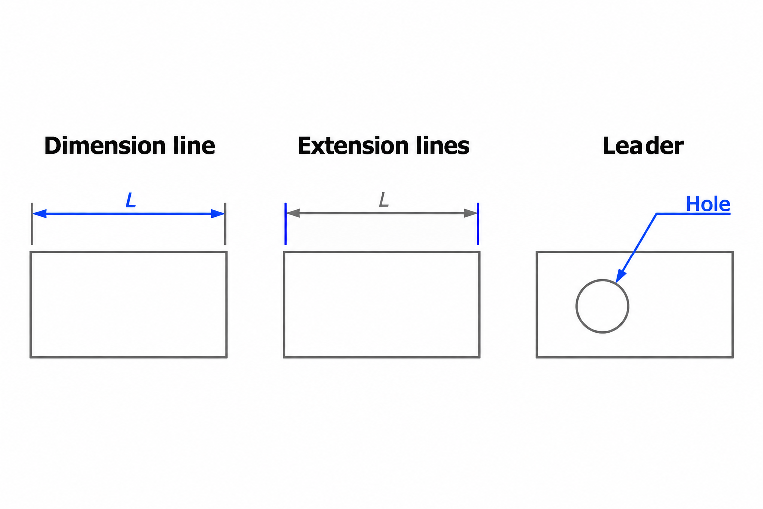
A line around the part depicts its outline. A dimension line describes a relationship associated with that geometry. A leader pointing to a hole identifies the subject of its note; the leader’s drawn length does not state the hole size.
Read the value, direction and units in that order
Start with the dimension text, then follow the arrows and extension lines to establish exactly what the value describes. A linear dimension can span part edges, feature centers or another defined pair of points. Angular dimensions describe angles, while radius and diameter annotations address different circular quantities.
For a hole, check whether the annotation describes its size or its location. A center mark helps identify the center; it does not itself supply the hole diameter. Likewise, a dimension between centers answers a different question from a dimension between the outer edges of two holes.
Check the drawing’s unit convention and relevant notes before using the value. CAD documentation illustrates why this matters: drawing dimension styles can use units different from those of the source model. An isolated screenshot or a number copied without its surrounding notes can lose that context.
A copper-bar example: overall length is not hole spacing
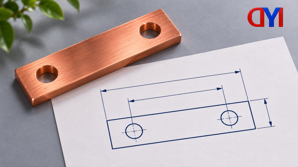
Imagine a simple rectangular copper bar with two circular holes. Label its overall length L, the distance between the hole centers P, and the diameter of a hole D. These labels are teaching identifiers, not dimensions from a customer project.
- L: trace the extension lines to the bar’s end faces. This describes the overall length.
- P: trace the references to the hole centers. This describes their center-to-center spacing.
- D: identify the diameter annotation and the hole to which it applies. This describes hole size.
Knowing L does not supply the missing P or D. Similarly, a hole-size note does not locate that hole along the bar. If the drawing does not clearly identify the required relationship, mark the ambiguous feature and ask the drawing owner to resolve it.
When discussing DONGYAO’s custom grounding copper bars, include the complete drawing context rather than a cropped dimension alone. Keep the units, referenced features, relevant notes and requested geometry together. The product’s drawing-customization context does not establish an unstated tolerance or inspection requirement.
References
- Autodesk AutoCAD: dimension components and dimension types.
- Autodesk Inventor: drawing dimensions, styles and measurement units.
For related conductor products, view the product categories.