Learning how to measure flatness starts with the surface and its required condition: define both, acquire readings across the surface, and evaluate its form with the specified method. Do not automatically call the largest minus the smallest raw height reading “flatness.” The setup can add orientation effects, and the sampling pattern can miss parts of the surface.
For a planar surface, the basic flatness zone lies between two parallel planes. The requirement concerns that surface’s form, rather than its orientation to an external datum. The measuring equipment still needs a suitable reference; a datum-free form requirement does not make the measurement reference-free.
How to measure flatness: define the requirement first
Identify the exact face, the extent of the requirement and the state in which the part is to be evaluated. Keep the drawing, its stated standard and the applicable inspection procedure with the job. This guide concerns a planar surface, rather than a derived median-plane control.
If the drawing specifies flatness per unit area or a flatness tolerance per unit length, record the actual region and definition. Clarify how any local requirement relates to the whole-surface requirement. Do not invent an inspection window or extend a local allowance across the part by assumption.
Choose the method and control the setup
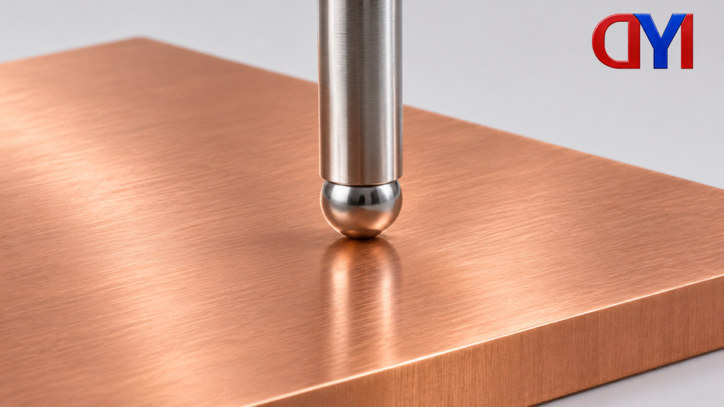
An indicator and a coordinate measuring machine (CMM) can both contribute to a flatness check, but they acquire information differently. Select the method for the surface access, required evaluation and available measurement capability.
| Approach | Information acquired | Key question |
|---|---|---|
| Indicator with a reference setup | Height variation along the explored paths | How are the reference, part orientation and measuring movement controlled? |
| CMM | Coordinates from the sampled surface | Which points or scans and which evaluation procedure represent the required surface? |
Prepare the contact and reference surfaces according to the inspection procedure. Record the support locations, any restraint and the surface state. Keep those conditions identifiable when comparing measurements; a result without its setup description leaves an important part of the method unstated.
For an indicator check, establish the reference and identify how the procedure handles the measured face’s orientation. A sweep over a part placed in an arbitrary orientation can mix form variation with tilt relative to the measuring plane. Mahr’s guidance specifically warns that a staged measurement can fail to separate flatness and parallelism effects.
For a CMM check, establish the surface extraction and evaluation in the measurement program. Naming the instrument is insufficient: the report should identify what was sampled and how those coordinates became the reported result. Use the applicable procedure rather than assuming a fitting option is interchangeable with another evaluation.
Distribute sampling across length and width
A few isolated readings describe only the locations explored. Plan coverage over the required surface, including relevant interior and boundary regions, rather than concentrating readings in one easy-to-reach area. Keep the point pattern or scan paths with the result.
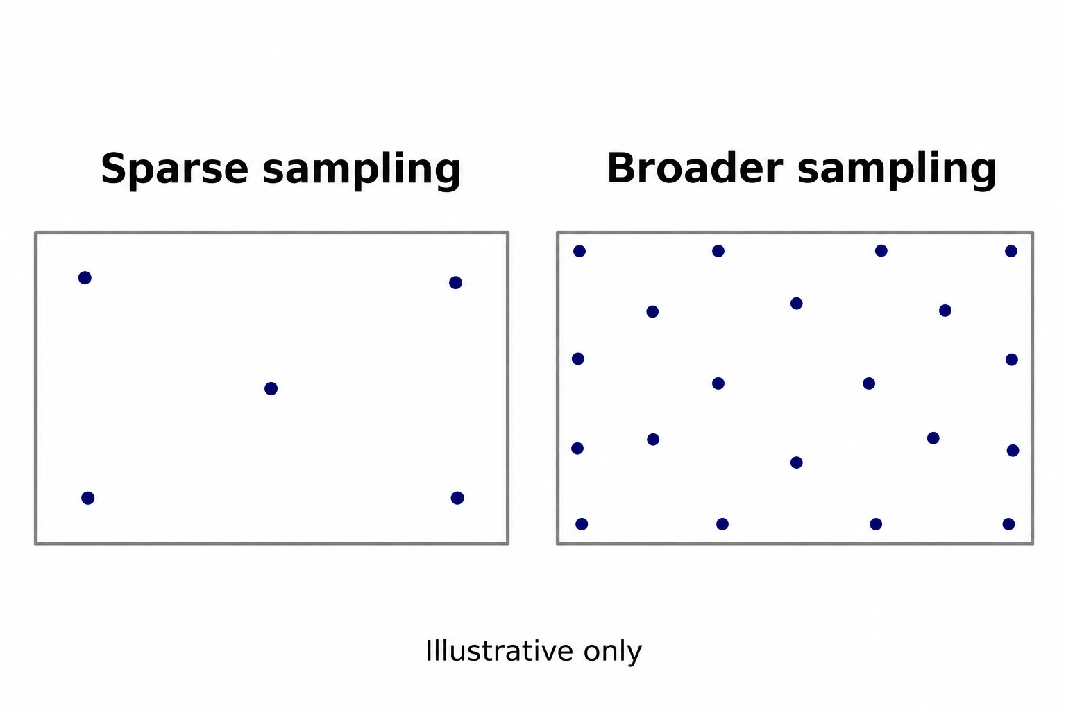
Mahr’s surface-plate example explains that a pattern covering outer and inner regions can still miss areas between measurements. Treat the coverage plan as part of the evidence for the result. There is no universal sampling pattern supplied by the drawing-independent examples in this guide.
Separate a numerical span from the required evaluation
Suppose an evaluation has produced the following hypothetical signed departures from its established plane: −0.004, +0.003, +0.001 and −0.002 mm. Their span is:
0.003 − (−0.004) = 0.007 mm.
That arithmetic is straightforward. Its meaning depends on the established plane, the evaluation and the sampled region. The example is not a minimum-zone calculation, a recommended number of points, a drawing tolerance or an actual inspection result. The four-value span alone cannot establish that an entire surface meets its flatness requirement.
The reference system also contributes to the measurement’s potential error. Document the relevant instrument and reference information and the uncertainty basis used by the inspection procedure. An acceptance decision needs that context alongside the reported value.
Keep a report that another inspector can interpret
A useful record connects the result to the requirement and its acquisition conditions. The following fields provide a compact reporting framework:
- The drawing revision, controlled surface and whole-surface or local extent.
- The support, restraint and surface condition.
- The instrument, reference and point or scan pattern.
- The orientation treatment and evaluation method.
- The result, units, uncertainty basis and applicable acceptance requirement.
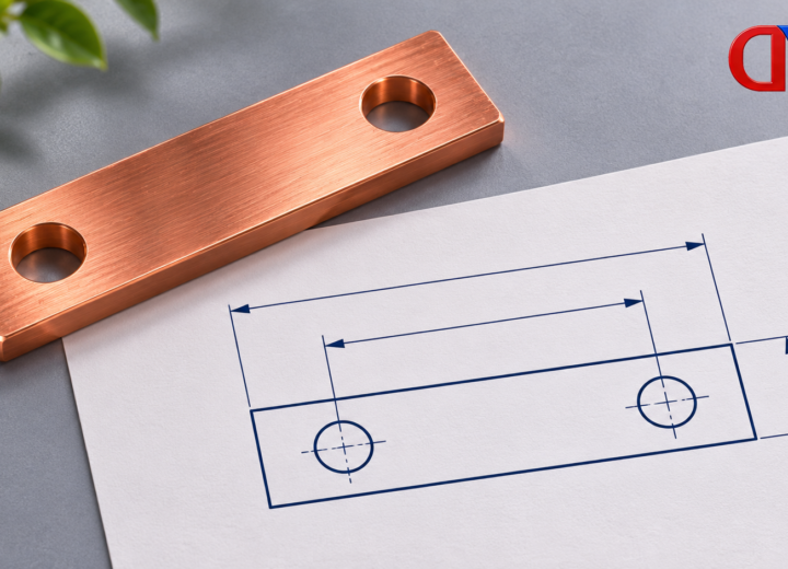
For a drawing discussion involving DONGYAO’s custom grounding copper bars, mark the intended face and supply the required condition and inspection definition. The product listing establishes a relevant drawing-customization context; it does not establish a flatness capability or an in-house measuring system.
References
- KEYENCE: form controls and the planar flatness zone.
- KEYENCE: indicator and CMM flatness measurement.
- Mahr original gaging text: reference and orientation effects (Section N, pages 5–6).
- George Schuetz, Mahr: surface-plate sampling and reference limitations.
For related conductor products, view the product categories.