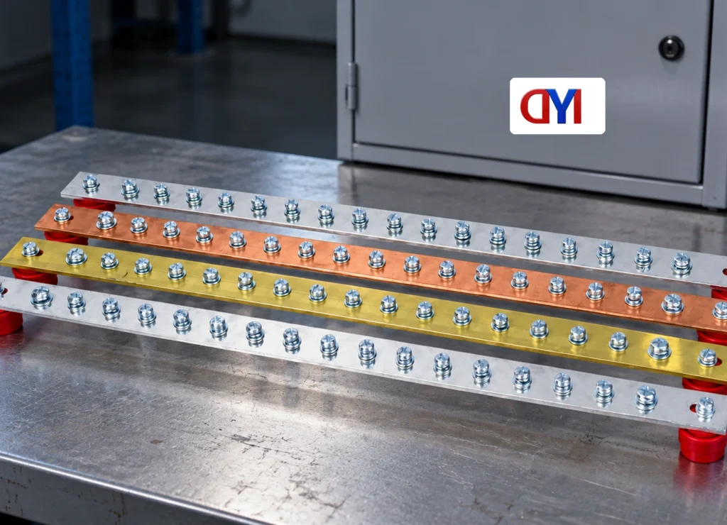
When a panel builder in Leeds, Arun, encountered an open protective path during a cabinet check, the copper bar looked correctly installed. In this illustrative scenario, its insulating supports had been mistaken for an enclosure bond. The correction was to restore the documented protective connection and verify the entire path.
Summary: A grounding busbar needs a defined protective function, compatible terminations and a documented bond. OSHA 29 CFR 1910.304 requires the grounding path to be permanent, continuous and effective. Bar width alone cannot establish compliance; inspect the bar, terminals, supports and intended path as one arrangement.
Define the grounding function before choosing dimensions
A power bus distributes normal operating current. A protective grounding busbar connects conductors and equipment associated with a protective path. A neutral bar has another function and must not be casually joined to protective metalwork at every location. Establish the system arrangement and approved bonding point before installation.
The existing explanation of what a grounding bar does introduces these distinctions. For a new cabinet, the installation drawing should identify each incoming conductor, its function, its termination and the connection to the wider protective system. A familiar-looking green wire or copper strip does not replace that schedule.
ASTM B187/B187M can define conductor stock requirements. It does not size the finished grounding assembly or determine where neutral bonding is permitted. Fault duty, applicable electrical rules, equipment instructions and the protective-conductor design must be considered separately.
| Item | Its function | Frequent specification error |
|---|---|---|
| Grounding busbar | Common termination point for the specified protective arrangement | Selecting only by overall length |
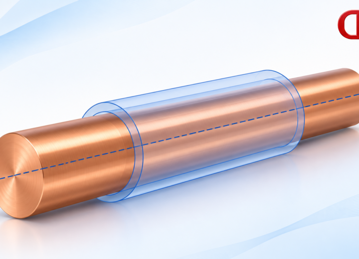
| Insulating support | Positions or isolates the bar mechanically | Treating it as a conductive enclosure bond |
| Lug and fastener | Terminates a compatible conductor | Matching only the bolt diameter |
| Bonding conductor or approved bond | Connects specified conductive parts | Assuming paint or mounting hardware creates the path |
Match lugs, holes and working space
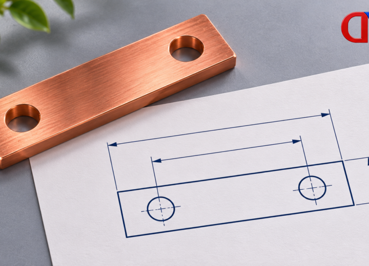
Record conductor material and size, lug type, hole diameter, pitch, fastener arrangement and tool access. OSHA 1910.303(c) requires connections to be made without damaging conductors and requires terminals for multiple conductors to be identified for that purpose. Do not place two conductors under a termination simply because they fit.
For a dimensional example, two lug holes on 25 mm centers cannot be accepted against a 30 mm hole-pitch drawing without an approved design change. The 5 mm mismatch is a fit problem, not something to solve by bending the lug or enlarging holes on site. These figures are illustrative, not a recommended pitch.
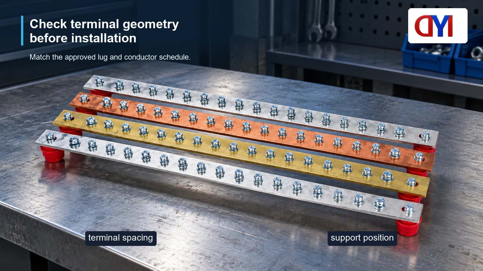
Provide enough room to insert the conductor, seat the lug flat and apply the specified tool. Keep cables supported so their weight does not distort the termination. Confirm whether coatings, washers and fasteners belong to the approved connection system before substituting them.
Separate mounting checks from bonding checks
Locate the bar where inspection and maintenance are practicable and where cables can be routed without sharp bends or strain. Use the approved supports and mounting hardware. The support spacing must reflect the equipment design and expected mechanical loading, including fault forces where applicable.
An insulating foot can be entirely appropriate, but it means the required enclosure bond must be established by the documented arrangement. Conversely, a metal mounting bracket is not automatically an accepted protective connection through a painted enclosure. Inspect the actual conductive path and relevant equipment instructions.
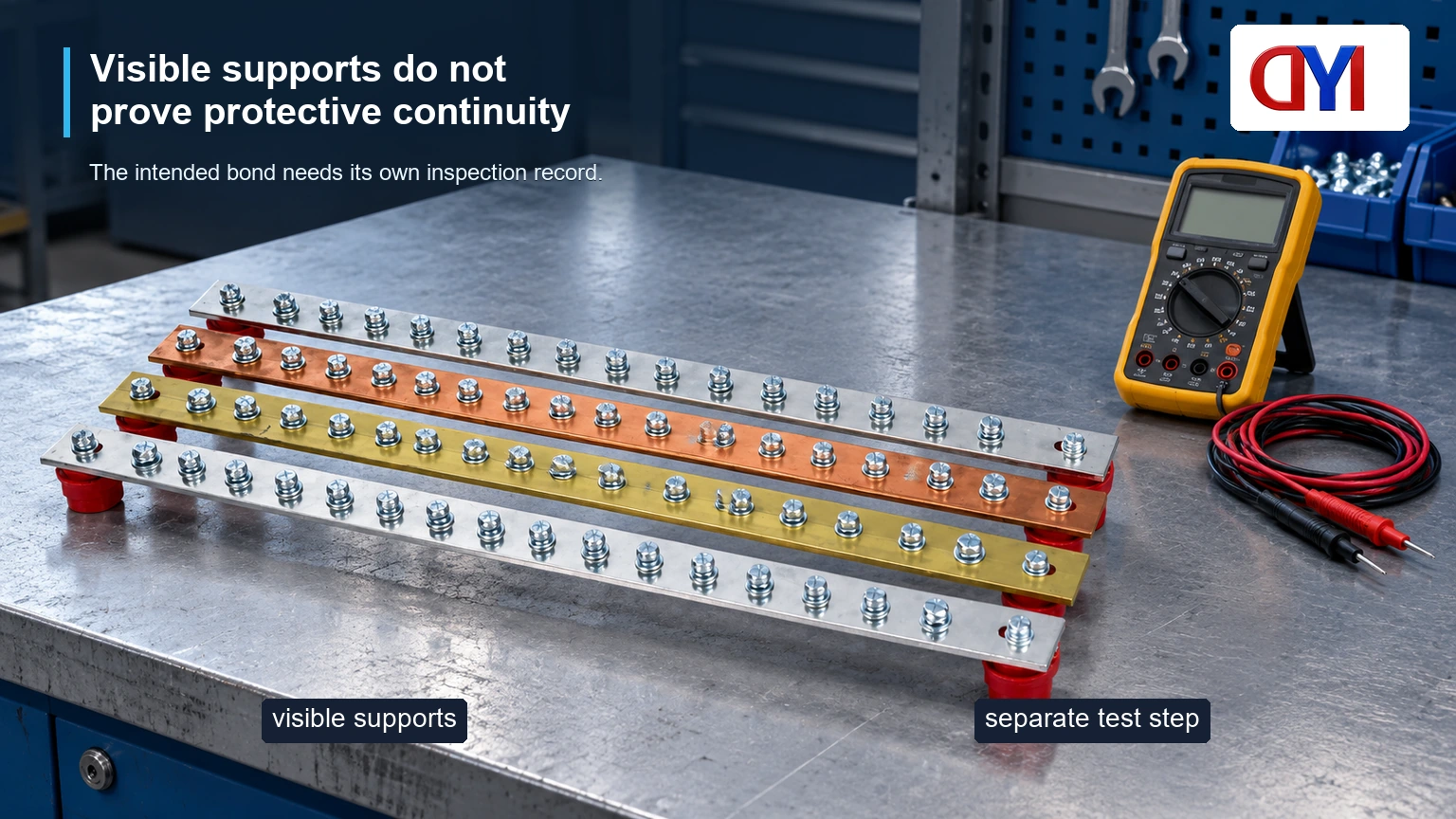
A continuity indication verifies only the path and conditions actually tested. It does not prove prospective fault withstand or establish an earth-electrode resistance. Specify test points, instrument method and acceptance limits from the applicable assembly requirements. Keep the readings with the cabinet identification and drawing revision.
Installation and inspection checklist
| Stage | Check | Record or acceptance basis |
|---|---|---|
| Before installation | Function, conductor schedule and approved drawing | Current controlled revision |
| Mechanical mounting | Supports, position, access and hardware | Equipment instructions and approved layout |
| Termination | Lug, conductor range, contact face and fastener method | Connection-system documentation |
| Bonding review | Intended path to enclosure and protective system | Electrical design and applicable rules |
| Final verification | Specified continuity and other assembly tests | Defined test points, limits and results |
Installation work should be performed by qualified personnel with the equipment isolated and verified safe. Do not infer that a resistance test authorizes work on an energized assembly. A visual checklist and an electrical test serve different purposes; both should be tied to an identifiable configuration.
Standards and the purchase decision
The NEC is adopted and amended by jurisdictions, so the applicable edition and local requirements matter. Article 250 addresses grounding and bonding, but no universal bar dimension follows merely from that article number. Have the designer identify the relevant conductor sizing, bonding and equipment provisions for the project.
US OSHA workplace requirements and ASTM material specifications have different scopes. Neither constitutes a product listing for an untested cabinet. Avoid purchasing against a vague statement such as “NEC copper bar” without the actual equipment and installation requirements.
Before ordering, resolve four items: protective function; material and geometry; approved terminal/support arrangement; and final verification records. DONGYAO’s cabinet grounding strip and custom grounding-bar range are sourcing references. Confirm the exact assembly details against the project drawing.
Frequently asked questions
What is the difference between a grounding bar and a bus bar?
Busbar is a general conductor term. A grounding bar has a specific grounding or bonding function in its designed system. It should not be treated as interchangeable with a power or neutral bus solely because the metal shape is similar.
What are the NEC requirements for ground bus bars?
Requirements depend on the adopted NEC edition, equipment and grounding arrangement. Relevant provisions address grounding, bonding, conductor sizing and approved connections. The design must identify the actual provisions rather than cite a generic compliance claim.
How to install a grounding bus bar?
Follow the approved layout and equipment instructions with the equipment safely isolated. Mount the correct supports, install compatible terminations and establish the documented protective path. Complete the specified inspections and tests before service.
How to size a grounding bus bar?
Use the applicable protective-conductor and equipment design requirements, including fault duty and terminal needs. Width, thickness, holes and support spacing all affect the result. A continuous-current table for a power bus is not automatically suitable.
What mounting hardware is needed for a grounding busbar?
Use the supports, brackets and fasteners specified by the assembly design. The choice depends on whether isolation or a conductive mounting path is intended. Confirm corrosion compatibility and mechanical loading as well as fit.
How should lugs and hole spacing be matched before installation?
Compare lug hole count, diameter and pitch with the controlled bar drawing. Also check conductor range, contact area, tool access and fastener requirements. Resolve any mismatch before fabrication or installation.
References
- 29 CFR 1910.304: wiring design and grounding paths
- 29 CFR 1910.303: equipment and terminations
- ASTM B187/B187M: copper conductor stock
A grounding bar is accepted through its complete path, not its appearance. Send DONGYAO the approved drawing with the conductor schedule and inspection requirements for a supply review.
For related conductor products, view the product categories.