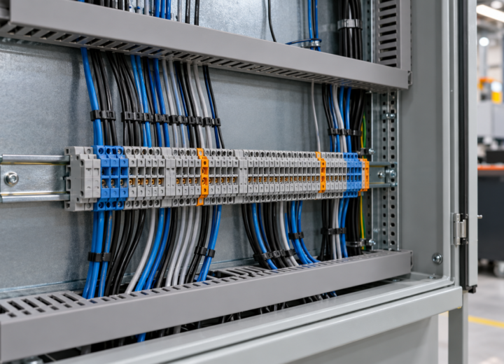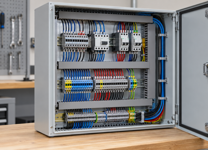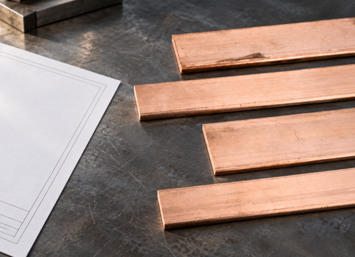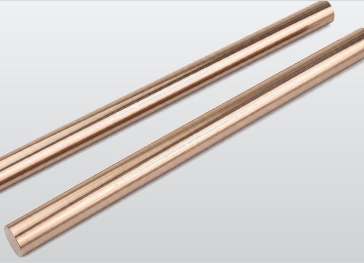
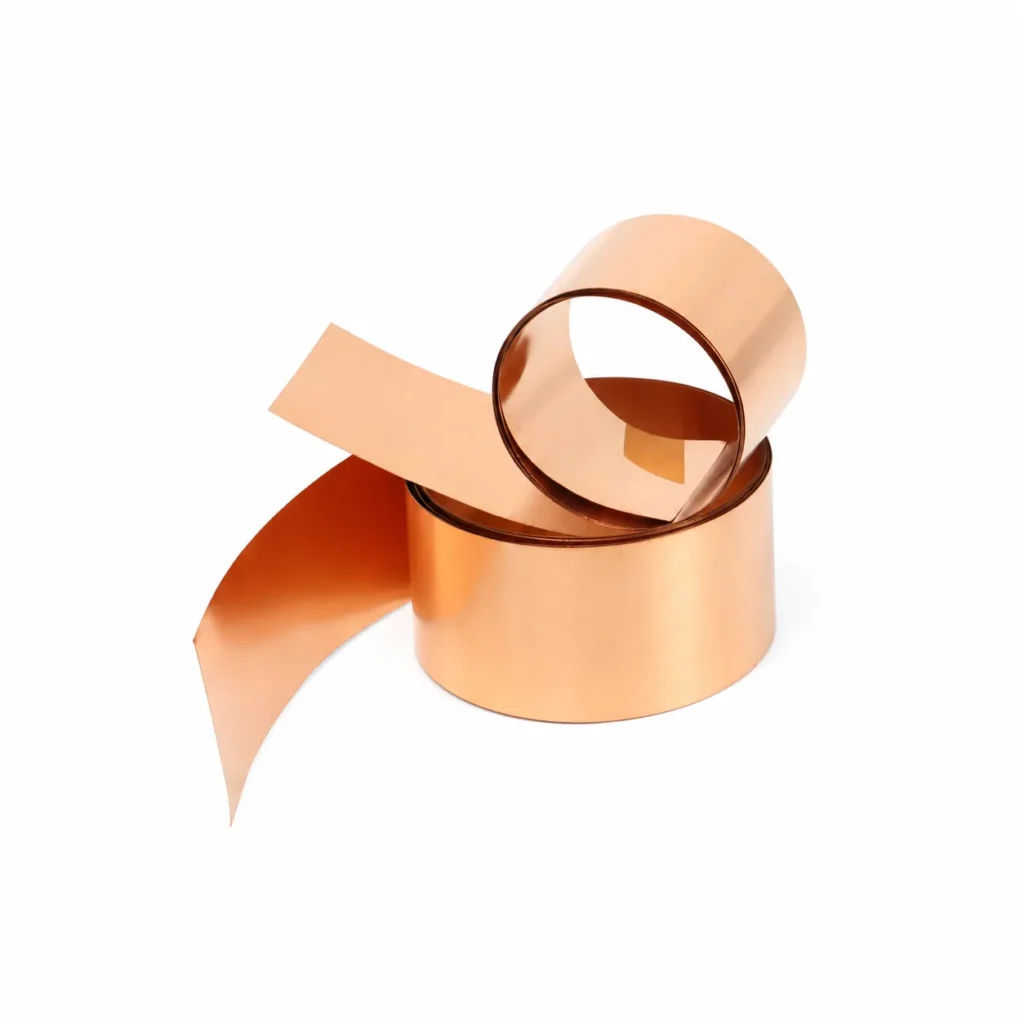
When a switchgear design engineer in Rotterdam encountered recurring cover interference during a retrofit build, she asked the shop to add threaded mounting points after formed copper links had already arrived. The screws started cleanly, but several heads sat proud of the cover; the visible failure looked like a fastener problem until the drawing review showed that the bend datum, thread location and seating recess had never been coordinated.
The reversal came when the team treated the conductive part as an assembly interface rather than a flat strip with secondary holes. By defining the final formed envelope first and then locating machining features from controlled datums, the buyer could compare like-for-like quotations and the fabricator could plan the sequence without guessing at hardware clearance.
Summary: A CNC Machining Forming Copper Bus Bar should be specified as one drawing-controlled feature system, not as independent milling, bending and hole operations. A Custom CNC Copper Bus Bar with Tapping and a Custom CNC Copper Bus Bar with Counterbore need explicit thread, mating-hardware, datum and inspection instructions; ASTM B187/B187M addresses copper bar material forms, while ASTM B193 is a resistivity test method rather than a machining rule. The practical action is to release one approved drawing package that defines the final formed state before process planning begins.
CNC Machining Forming Copper Bus Bar depends on one controlled datum chain
A conductive link may look simple in a flat layout, yet its functional surfaces are often established only after a flange, offset or bend is made. The released drawing should identify the part orientation, bend direction, forming sequence, primary and secondary datums, and the final envelope that must fit inside the assembly.
That instruction changes how milling and drilling are located. A hole that is correct from a pre-form edge can become wrong from the mating face after bending, so the manufacturer needs to know whether a feature is controlled in the blank, in an intermediate formed state, or in the final condition.
For a CNC Machining Forming Copper Bus Bar, a workable route can use CNC machining for profiles and interfaces, controlled forming for the three-dimensional shape, then secondary work only where the drawing allows it. The route is not universal: access, deformation risk, burr direction, plating requirements and the functional datum can all alter the order.
Buyers can see the broader relationship between machining features and formed conductive geometry in this guide to custom copper busbar machining and design. Its useful lesson for a drawing review is that each feature should have a functional reason, not merely a coordinate.
A Custom CNC Copper Bus Bar with Tapping needs a defined thread-and-finish sequence
Tapping is not adequately described by a hole diameter alone. The drawing or accompanying specification should state the thread designation, any required class or fit, usable thread depth, engagement requirement, applicable face, burr and chip-control expectation, and whether the thread is made before or after finishing or plating.
Thread depth and engagement serve different functions; the first is a manufactured geometry, while the second depends on the mating fastener and assembly stack. Rather than copying a nominal recommendation across products, the buyer should identify the selected hardware, the loading context and any accessible inspection condition in the approved design record.
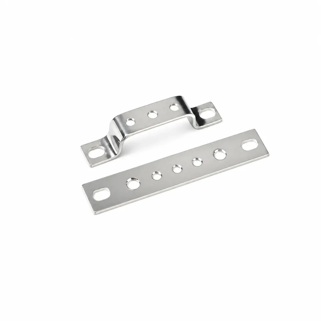
A Custom CNC Copper Bus Bar with Tapping also needs a clear finish sequence. If a surface treatment is specified, the drawing should make clear whether masking, post-finish thread cleaning, protection of contact faces, or another approved sequence applies; an unqualified request for a “finished thread” leaves avoidable interpretation.
Chip and burr control deserve the same functional language. A requirement may call for no loose chips in a particular cavity or no interfering burr at a seating face, but it should not imply that every part needs the same method; visual chip checks, gauges or other controls are examples only when selected by the approved drawing.
| Feature relationship | What the drawing should establish | Why it affects the assembly |
|---|---|---|
| Formed face to thread | Finished datum and feature orientation | Prevents a correct flat pattern from becoming an inaccessible thread |
| Thread to finish | Thread designation, usable depth and finish sequence | Clarifies mating and post-process handling |
| Thread to burr control | Functional surface and chip/burr condition | Protects seating and enclosure interfaces |
The comparison is commercial as well as technical. A quote based on an incomplete thread callout may appear lower because the supplier has priced a different assumption, whereas an explicit drawing makes setup, inspection planning and change control visible before a late assembly issue creates rework.
A Custom CNC Copper Bus Bar with Counterbore is an assembly interface, not a default recess
A counterbore creates a controlled relationship between a fastener head, a functional surface and the surrounding assembly. It therefore requires drawing-defined diameter, depth, datum, functional surface, mating hardware and inspection condition; it is not safe to assign a universal counterbore dimension, depth or seating rule to copper parts.
In a Custom CNC Copper Bus Bar with Counterbore, the question is not simply whether the screw head is recessed. The question is which face establishes the seating plane, what hardware is intended, whether a washer or coating changes the stack, what clearance is needed in the final envelope, and how the approved drawing asks that relationship to be checked.
Counterbores are particularly sensitive when located near a bend or on an offset surface. The manufacturing plan must preserve the stated datum transfer through forming, account for tool access and burr direction, and avoid treating a flat-state coordinate as proof of final-state clearance.
A CMM, a functional gauge, a depth-measuring method or a visual chip check may be appropriate examples of inspection methods, but none should be promised by default. The approved drawing should select the inspection condition that demonstrates the interface the assembly actually uses.
It is helpful to separate two questions that are often merged in a purchase request: whether the fastener can enter the feature, and whether its installed head is compatible with the surrounding enclosure or contact arrangement. The first is related to hole and hardware compatibility; the second depends on the seating plane, available clearance and final part orientation.
That distinction also improves change control. If hardware, cover thickness or the locating face changes, the engineering team can identify the counterbore interface as an affected design item instead of asking a supplier to make an unexplained “same as before” modification.
For related process context, buyers can review CNC cutting, bending and punching for custom copper bus bars. The present issue is narrower: a recess becomes valuable only when its geometry is tied to the actual mating hardware and final formed part.
Drawing review links forming, machining and inspection to the final assembly
The most effective request for quotation is an approved package, not a list of operations. It should include a revision-controlled drawing, material and condition where applicable, the final formed view, feature callouts, mating hardware information, finish instructions, quantity and any assembly-critical notes.
For a CNC Machining Forming Copper Bus Bar, the review should first trace one datum chain from blank through forming to the final interface. That trace exposes whether a coordinate needs to be evaluated before forming, after forming, or by a fixture that represents the final mating condition.
| Review item | Decision to record | Cost or schedule implication |
|---|---|---|
| Feature sequence | Machine before or after forming, with reason | Determines tooling access and setup count |
| Counterbore interface | Hardware, seating face, datum and inspection condition | Reduces late cover or fastener interference risk |
| Threaded connection | Designation, required fit if any, depth and finish sequence | Aligns supplier assumptions with the mating part |
| Final envelope | Formed state and clearance-sensitive areas | Supports fixture planning and assembly fit review |
ASTM B187/B187M covers copper bus bar, rod and shapes; it is useful material-form context, not a complete process instruction for a custom part. ASTM B193 is a method for measuring electrical resistivity of electrical conductor materials, so it is not a machining, tapping or counterbore standard.
IEC 61439-1 applies to low-voltage switchgear and controlgear assemblies. Neither that assembly standard nor the ASTM documents determine a standalone part’s current rating, tightening torque, counterbore depth or final compliance; those conclusions depend on the intended assembly, design evidence and applicable project requirements.
A useful drawing-review rhythm is to examine the part in its final orientation, then read each assembly-critical callout back to its controlling datum and mating condition. This is more informative than a flat-pattern-only check because it makes clear whether a bend, offset, hardware head or cover is the actual constraint.
Suppliers also need revision discipline around these relationships. A revised 3D model without an updated callout, or a changed hardware selection without a corresponding seating instruction, can create a perfectly repeatable manufactured feature that no longer represents the released assembly intent.
Industrial buyers can ask four focused questions before releasing an order:
- Which final faces locate the formed part in the assembly?
- Which thread and counterbore features are tied to named mating hardware?
- Where must burr direction, chip condition or surface protection be controlled?
- Which inspection condition demonstrates the final functional interface?
DONGYAO (Zhejiang Dongyao Electronic Co., Ltd.) supports drawing-based and OEM conductive parts for teams that need these decisions reflected in a manufacturable request. For a CNC Machining Forming Copper Bus Bar, early clarification is usually less costly than changing a formed and finished component after the assembly has exposed an assumption.
Frequently Asked Questions
What must be specified for a custom tapped copper bus bar?
A Custom CNC Copper Bus Bar with Tapping should identify the thread designation, any required class or fit, usable depth, expected engagement, feature datum, burr/chip condition and finish or plating sequence. The mating hardware and final assembly access should be part of the review, because a technically cut thread can still be unsuitable at installation.
How should a counterbore be called out on a formed copper part?
A Custom CNC Copper Bus Bar with Counterbore needs a drawing-defined diameter, depth, datum, functional surface, mating hardware and inspection condition. Its geometry should be checked against the final formed envelope, not inferred from a generic fastener table.
Should copper busbar features be machined before or after forming?
The correct sequence depends on the specified datum, tool access, bend direction, burr control and finished interface. A CNC Machining Forming Copper Bus Bar drawing should state the final geometry and the features that are functionally controlled after forming, allowing the manufacturer to choose a defensible route.
Do ASTM B187/B187M or IEC 61439-1 set a copper part’s torque or current rating?
No. ASTM B187/B187M addresses copper bar, rod and shapes, and IEC 61439-1 concerns low-voltage switchgear and controlgear assemblies; neither supplies a standalone torque, current rating or counterbore depth for a custom component.
References for copper busbar material and assembly control
- NIST, Physical Reference Data: Copper
- Copper Development Association, Electrical Copper
- Copper Development Association, Standards & Specifications
- ASTM B187/B187M-20 product page
- IEC 61439-1 publication information
Good conductive-part sourcing begins with the final interface: geometry, hardware and inspection must describe the same assembly reality.For a drawing review or an OEM quotation for a CNC Machining Forming Copper Bus Bar, contact DONGYAO with the approved drawing package and intended mating condition.
For related conductor products, view the product categories.