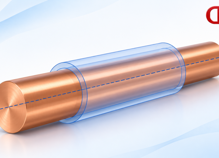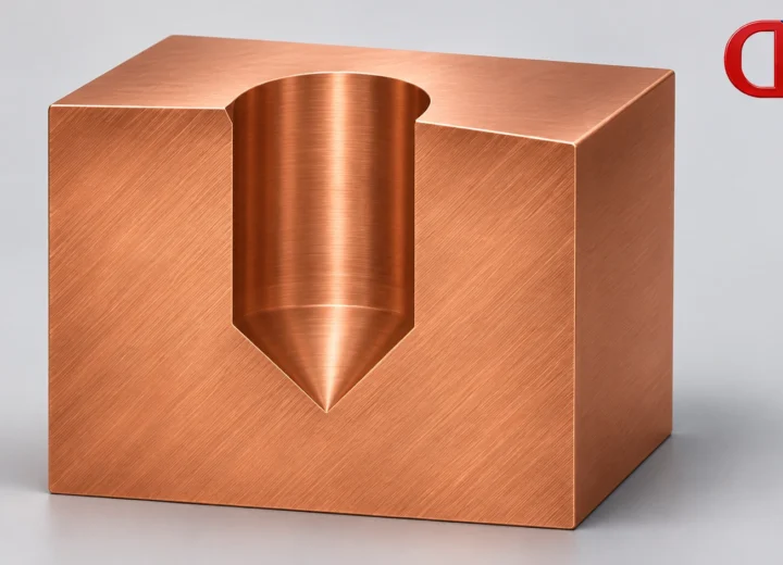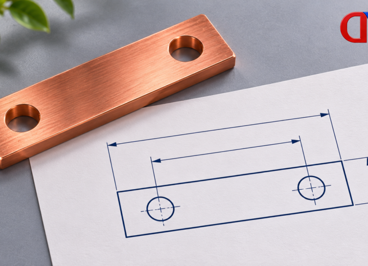
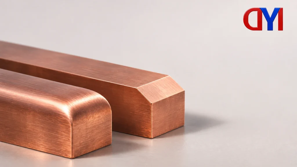
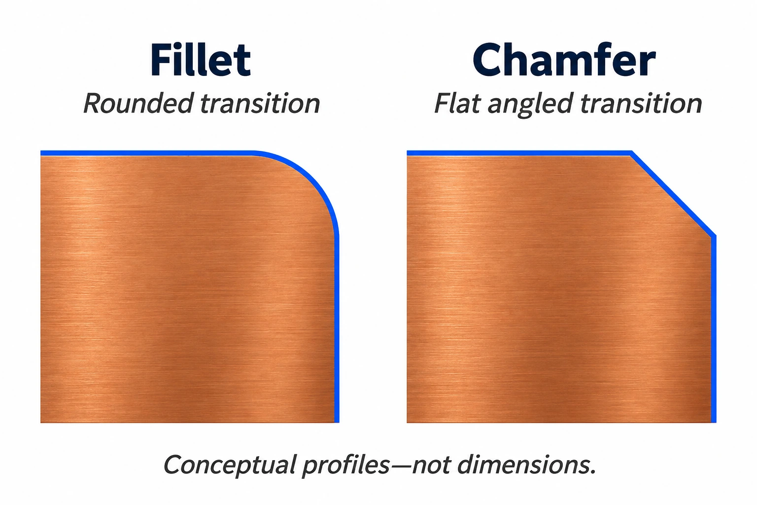
The fillet vs chamfer distinction starts with geometry: a fillet creates a rounded transition, while a chamfer creates a flat, angled transition. Either can change a sharp edge, but choosing between them requires the edge’s function, its relationship to mating parts and the manufacturing route.
Fillet vs chamfer: identify the intended shape
A fillet can round an internal corner or an external edge. Autodesk’s Inventor documentation includes edge, face and full-round fillets, so the word alone does not completely define the feature. A simple constant-radius edge and a more complex face transition need different geometric information.
A chamfer replaces the corner with a flat, sloping face. Autodesk describes chamfers through either two distances or a distance and an angle. The drawing should make the intended size and orientation clear instead of relying on the appearance of a shaded model.
“Bevel” and “chamfer” also overlap in usage. AutoCAD’s documentation treats both as angled transitions. A buyer should therefore ask what a bevelled or chamfered edge means on the specific drawing, rather than applying a universal rule based on how long the sloping face looks.
The geometric description remains useful across these naming differences. “Rounded external transition” identifies a different result from “flat angled transition,” even before the designer supplies the dimensions.
Compare the information needed to define the edge
| Drawing description | Geometry identified | Information still needed |
|---|---|---|
| Fillet | A rounded transition. | Its location, rounded form and required size. |
| Chamfer | A flat angled transition. | The distances or distance-and-angle definition and orientation. |
| Bevel | An angled transition under the terminology used here. | The actual face geometry rather than a presumed length-based naming rule. |
| Remove burrs | A general handoff instruction. | Whether the proposed edge shape and extent are permitted. |
This comparison is a drawing-review aid, not a standard callout template. A feature name identifies a kind of shape; the drawing still needs to locate and define the required result. The same-looking edge in a rendering may represent different dimensions or functions.
Choose from the edge’s job
Handling: An exposed edge that people handle deserves deliberate treatment. Protolabs discusses rounded and sloped edge breaks as alternatives to an undesired sharp edge. The useful question is which surfaces people touch and what finished edge the design requires. A rounded appearance alone is not a safety certification.
Mating: An edge near an assembly must be considered with the adjoining component. In a drawing review, identify the entering edge, nearby corner and intended contact surfaces together. The choice should preserve the required fit; an edge treatment selected only for appearance may not answer that assembly question.
Load transition: Protolabs notes that fillets can spread loads and that sharp corners can act as stress raisers. This supports considering the transition during design. It does not establish a fixed strength increase, fatigue life or acceptable radius for a particular copper or aluminum component.
Machining: Internal radii can also follow from milling-tool geometry. An internal pocket corner therefore raises a different manufacturing question from a small external edge break. A supplier’s preference for a simpler external chamfer is useful process guidance, but it is not proof that every chamfer costs less than every fillet.
Put the choice back onto the drawing
Consider a custom bar with an exposed outside edge and a nearby mating region. Identify which edge needs handling treatment, which surfaces participate in the fit, and which transition carries a load-related requirement. The same edge feature need not answer all three.
The designer can identify each relevant edge on the drawing and provide its intended geometry. For a chamfer, that means an unambiguous distance-based or distance-and-angle definition. For a fillet, the model and drawing should define the required rounded form rather than leaving the supplier to select one from the feature name.
A general instruction to remove burrs should also be distinguished from a deliberately dimensioned edge feature during the handoff. Ask whether the instruction permits the proposed shape and size. That prevents a broad finishing instruction from silently replacing the designer’s geometric requirement.
For a custom copper-bar component, share those drawing locations and functions with the inquiry. The product category does not establish a standard radius, chamfer size or load capability. The useful result is agreement on the actual edge geometry before the manufacturing route and inspection details are settled.
Review an outside edge and an inside corner separately
Now add an internal pocket receiving another component to the same example. Its corner needs a defined relationship to that mating part, separate from the outside edge’s handling requirement.
For the pocket, ask the manufacturer to compare the defined corner with the proposed cutting route. The face and peripheral milling explanation distinguishes generated floors and walls from a tool name. If the proposed route leaves a different internal transition, the drawing owner must resolve that geometry rather than treating the change as an incidental deburring choice.
An angled recess around a hole raises a different issue again: it may be a deliberately defined head-seat feature. The counterbore versus countersink comparison addresses that task. A generic external chamfer description should not silently define a fastener seat.
Identify each edge’s location and function, define the intended geometry, and resolve any proposed manufacturing change with the drawing owner.
References
- Autodesk — About Chamfers and Bevels, geometry definitions.
- Autodesk — About Placed Features, fillet types.
- Protolabs — Design for Machining Toolkit, radii and design notes.
- Protolabs — Fillets vs Chamfers, edge-design considerations.
For related conductor products, view the product categories.