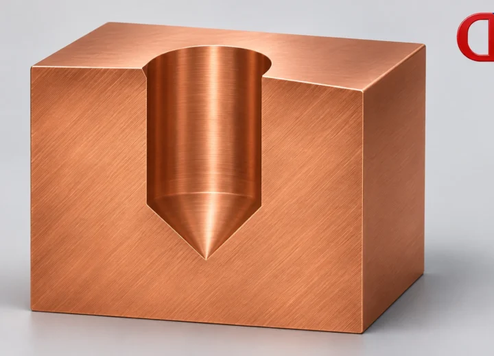
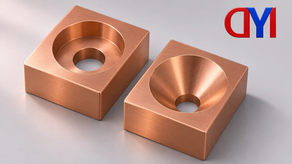
The counterbore vs countersink difference is the recess shape: a counterbore has cylindrical walls and a flat bottom around a smaller coaxial hole; a countersink has a conical entry. Choose the recess to match the intended fastener’s bearing geometry, then define its size separately from the smaller hole.
Counterbore vs countersink: compare the seats
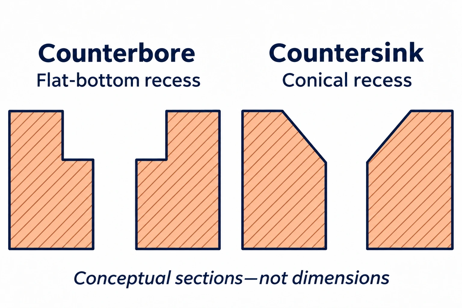
A counterbore provides a recessed, flat mounting surface. GD&T Basics identifies socket head cap screws as common hardware for this arrangement. In section, the enlargement looks stepped: vertical walls descend to an annular flat shoulder, with the smaller hole continuing beneath it.
A countersink presents a sloping, conical seat. Haas Tooling explains that a matching fastener angle allows the head to sit flush with or below the surrounding surface. The required angle comes from the selected hardware and design; it should not be inferred from the word “countersink” alone.
A spotface serves a related but different purpose. It creates a shallow, flat mounting area around a coaxial hole, for example where a washer needs a flat seat. Its purpose is to establish the bearing area, rather than necessarily bury a fastener head within the component.
That distinction helps avoid an unnecessary assumption: a flat seat does not automatically require the head to be recessed. The designer should identify whether the need is a mounting surface, a recessed head or a conical head seat.
Counterbore, countersink and spotface compared
| Feature | Seat geometry | Main drawing question |
|---|---|---|
| Counterbore | Cylindrical enlargement with a flat annular bottom. | What diameter and depth accommodate the intended recessed flat-bearing head? |
| Countersink | Conical entry around the smaller hole. | What opening and angle match the specified conical head and position? |
| Spotface | Shallow flat mounting area around the hole. | What bearing surface is required, without assuming the head must be buried? |
The smaller hole remains a separate feature in each row. Its diameter, termination and any thread requirement still need definition. This is why replacing one recess name with another is more than a wording change: the seat geometry can change while the central hole remains apparently similar.
Read the recess and the smaller hole separately
The counterbore symbol, ⌴, identifies the feature. GD&T Basics shows it with the counterbore diameter and depth. The symbol is a recognition aid; it does not supply the missing dimensions or replace the drawing’s governing conventions.
Autodesk Fusion’s Hole reference separates the underlying geometry into distinct fields: hole diameter and depth, counterbore diameter and depth, or countersink diameter and angle. This separation is useful when checking an inquiry, even when the part was created in another CAD system.
A note containing only the smaller hole diameter does not describe the complete recess. Likewise, a countersink diameter without its required angle leaves an important geometric input unresolved. Confirm which face receives the recess and where any stated depth begins.
Hole-entry shape also differs from thread designation and termination. Fusion treats hole type, tap type and extent as separate selections. A recessed entry therefore does not, by itself, tell the reader whether the smaller hole is tapped, clear or through.
Check the fastener against the section
Consider a copper component whose drawing requires a head below the top surface. This editorial example begins with the hardware drawing: identify its underside bearing shape and required head position. Then compare that information with the component’s section view and recess definition.
For a flat-bearing head in a counterbore, the review asks whether the specified recess accommodates the selected head at the intended position. For a conical head, it asks whether the seat angle and opening agree with the hardware. Neither answer follows from selecting a tool name.
The available material also belongs in that review. Show the overall thickness and recess extent together so the designer can assess the resulting section. There is no universal minimum remaining thickness supplied by this comparison; the actual component and loading requirements govern that decision.
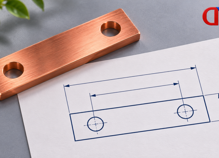
For a custom copper-bar component, send the identified fastener and complete recess requirements with the drawing. The product category establishes neither standard hole dimensions nor a fastener load rating. Resolving those geometric inputs gives the supplier a defined feature to discuss and inspect.
Resolve a mismatch between hardware and component records
Imagine a hardware drawing showing a conical underside on the selected head, while the component section shows a cylindrical enlargement with a flat shoulder. Both records might use the general phrase “recessed head,” but the bearing shapes differ. Resolve the hardware identity and intended seat before accepting the component feature.
The next question concerns head position. A flat mounting area provided by a spotface does not necessarily meet a requirement for the head to sit below the surrounding surface. Conversely, a recessed head requirement does not supply the missing diameter, depth or angle. Compare the actual section and complete feature definition rather than relying on the shared phrase.
Then check the central hole independently. If the requirement includes an internal thread, the tapped versus threaded hole explanation separates that result from the seat and production method. If the discussion is only about easing a sharp edge, use the edge-feature comparison rather than assuming a generic edge break defines a conical fastener seat.
This exercise identifies an inconsistency for the drawing owner to resolve. It does not prescribe a replacement fastener, a recess dimension or a remaining-section limit.
References
- GD&T Basics — Counterbore, geometry and callout.
- GD&T Basics — Spotface, flat mounting areas.
- Autodesk Fusion — Hole reference, separate geometric inputs.
- Haas Tooling — Countersinks, matching conical fastener seats.
For related conductor products, view the product categories.