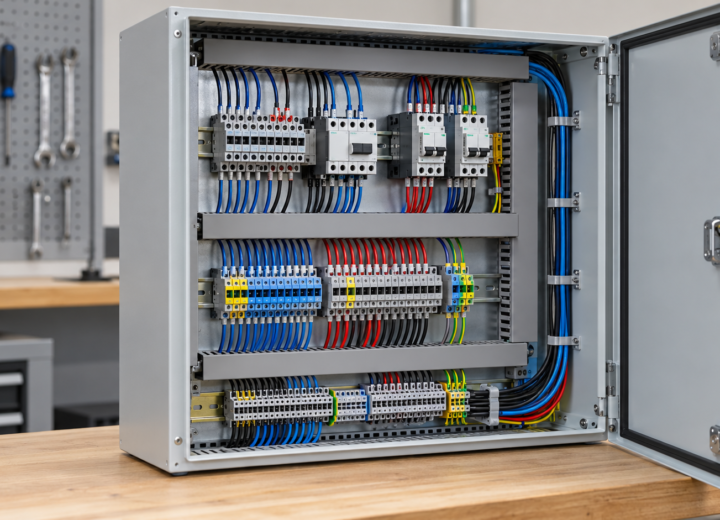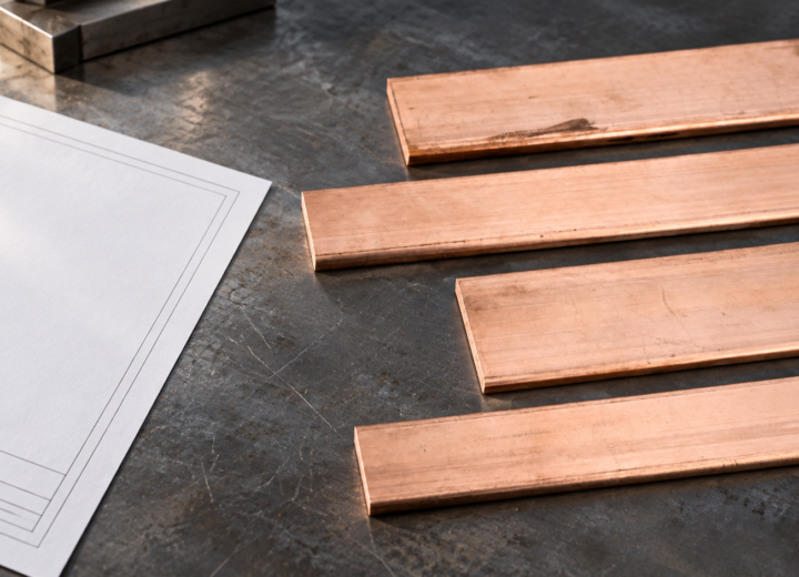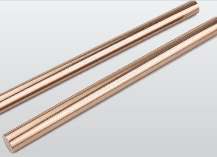
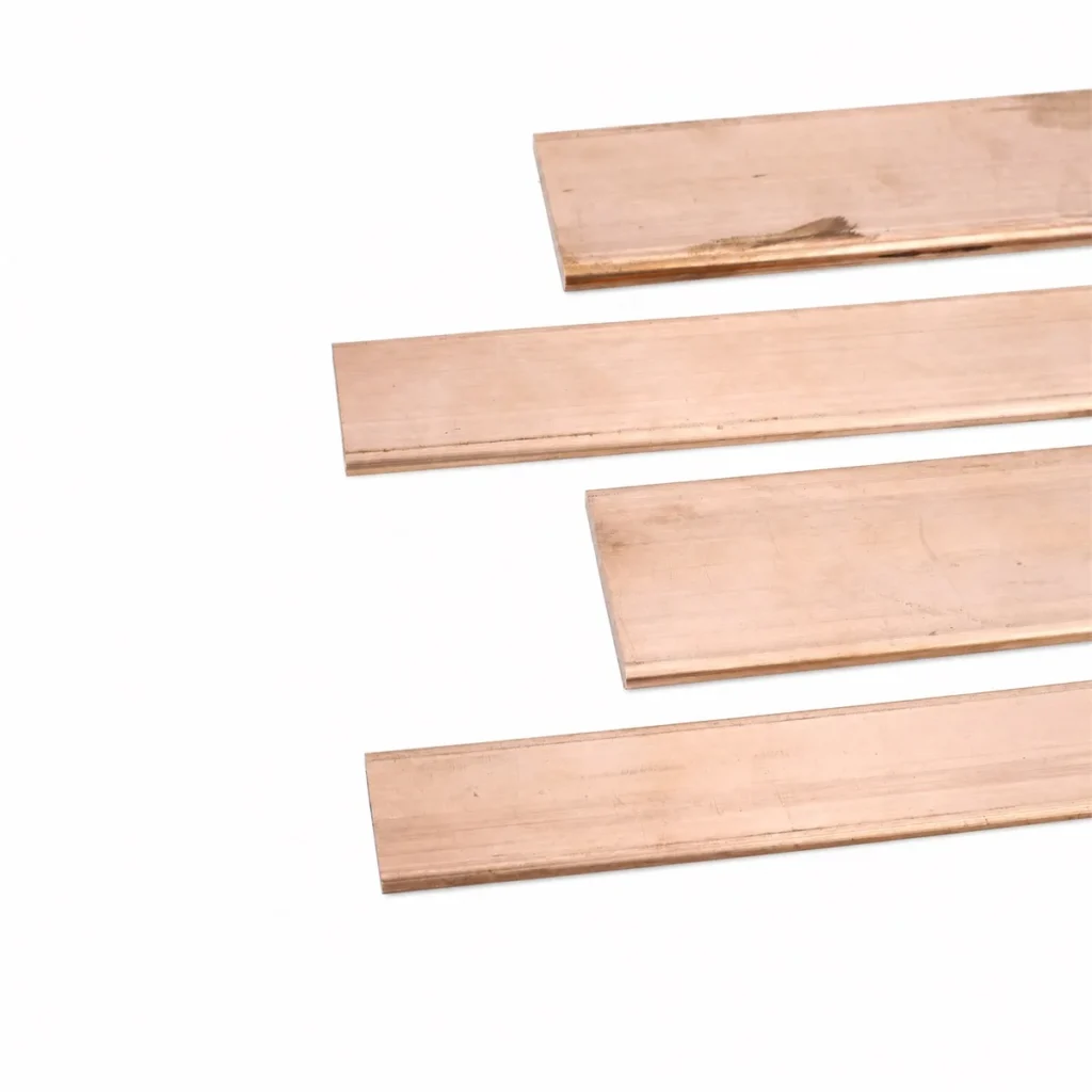
When a switchgear engineer in Rotterdam encountered loose contact alignment during a late panel fit-up, she asked the assembler to start each threaded copper connection by hand before the final hardware was installed. Two holes visibly refused to line up, and the bar tilted against its mating plate. The rapid failure looked like a machining defect.A drawing review reversed that conclusion: the threads had been made to their individual callouts, but the drawing had not established the functional datum path from the mounting face to the thread axes. The answer was not to demand an undefined “tighter” part; it was to control the relationships that let the interface assemble.
Summary: A Custom CNC Copper Bus Bar with Thread succeeds when the drawing identifies functional datums, the Tight Tolerance CNC Copper Bus Bar callouts control feature relationships, and Micron Precision CNC Copper Bus Bar language is translated into an approved inspection plan. ASTM B187/B187M addresses copper bus bar, rod, and shapes; it does not certify an individual part’s thread fit or final assembly. Buyers should release a drawing, inspection method, and change-control route together.
Threaded copper interfaces should start with a functional datum strategy
A threaded feature is rarely important in isolation. In an enclosure, battery pack, converter, or switchgear assembly, its usable position is defined by the faces, slots, bends, clearance holes, and mating hardware that lead to it.
That is why a drawing should distinguish datum features from convenient measurement edges. A primary mounting face can establish seating, a secondary edge can establish lateral location, and a tertiary feature can prevent rotational ambiguity; the order should match the way the part is located in the real assembly.
For a Custom CNC Copper Bus Bar with Thread, the useful question is whether the thread axis is positioned relative to the mounting plane and mating pattern, rather than merely whether a tap was produced. A position requirement, when the design needs one, communicates a relationship that plus/minus dimensions scattered from nonfunctional edges may not.
Thread engagement is also an interface decision. The drawing should state the thread designation, depth or usable engagement requirement where applicable, entry condition, mating fastener assumptions, and whether a stud, screw, insert, or other component carries the load. It should also make clear which faces must remain free of burrs, chips, plating buildup, or handling damage that could disturb seating.
Copper’s conductivity is a design advantage, but it is not a shortcut through interface engineering. NIST Physical Reference Data reports basic copper properties, while the Copper Development Association discusses electrical copper uses; neither source replaces a drawing-controlled joint definition or a released assembly procedure.
Early interface-development work is often more valuable than a late inspection dispute. Teams comparing a threaded design with punched, drilled, or formed features can review the relevant interface-development approach before fixing datums and process assumptions.
A Tight Tolerance CNC Copper Bus Bar needs relationship controls, not isolated numbers
A Tight Tolerance CNC Copper Bus Bar is best specified by tracing every critical feature back to the same functional reference frame. Hole-to-hole spacing, thread-to-slot location, contact-face flatness, and bend-to-thread position can all affect assembly even when each feature appears acceptable by itself.
Consider a bus bar that seats on a machined face, receives a threaded fastener, and clears a molded barrier. The relevant acceptance condition may combine seating, axis location, and clearance; controlling only the tapped hole diameter leaves the most consequential relationships open to interpretation.
Drawing notes should identify critical-to-assembly features and use unambiguous geometric controls where the design demands them. They should also separate manufacturing reference dimensions from acceptance criteria, so that a supplier does not convert a helpful layout number into an unintended inspection requirement.
The table below compares two specification habits. It is a planning aid, not a substitute for the purchaser’s approved drawing.
| Specification approach | What is controlled | Likely assembly consequence | Commercial implication |
|---|---|---|---|
| Independent dimensions from varied edges | Individual features, often without a common origin | Stacked variation can emerge at the mating interface | More clarification may be needed after first articles |
| Datum-based feature relationships | Functional face, locating edge, and feature axes | Acceptance follows the intended assembly references | Inspection planning can be quoted against a clearer scope |
| Tight Tolerance CNC Copper Bus Bar callouts on critical relationships | Only the interfaces that need closer control | Resources focus on fit, clearance, and contact geometry | Cost drivers can be reviewed before release |
There is a total-cost issue behind this discipline. A broadly restrictive drawing may increase setup, fixturing, measurement, and rejection risk without improving the joint; a targeted one can reduce downstream fitting iterations. Any savings calculation is illustrative until material condition, quantity, finish, inspection scope, and assembly risk are known.
Material language should stay equally precise. ASTM B187/B187M covers copper bus bar, rod, and shapes as a product specification. ASTM B193 is a test method for electrical resistivity of electrical conductor materials; it is not a certificate for a thread, a positional tolerance, or a completed bus bar assembly.
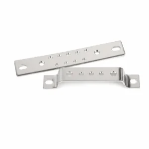
Micron precision wording must resolve into a measurable release plan
The phrase Micron Precision CNC Copper Bus Bar can be useful shorthand in a sourcing conversation, but it is incomplete as an acceptance requirement. It must be converted into named characteristics, datum references, applicable tolerances, sampling or quantity expectations, and an agreed measurement method.
“Micron” describes a scale, not an automatic manufacturing promise. A part can contain one exceptionally sensitive relationship and several ordinary, fit-for-function features; releasing all of them under an undefined precision claim can create conflicting expectations for machining, handling, coating, and inspection.
The inspection plan should match the drawing and the risk. A CMM may suit certain datum-related locations; dedicated gauges may suit a repetitive thread interface; visual burr and chip inspection may suit a specified edge condition. These are examples only, selected when the approved drawing and production plan call for them.
| Drawing question | Why it matters | Possible documented response |
|---|---|---|
| Which face locates the assembly? | It establishes the primary measurement reference | Identify the primary datum and its inspection setup |
| Which feature-to-feature relationship governs fit? | It reveals where variation affects mating | Use the drawing’s dimensioning and geometric controls |
| What is the thread’s functional engagement condition? | It distinguishes a tapped feature from a usable interface | Define designation, depth, mating condition, and applicable gauge method |
| Where is the precision claim actually needed? | It prevents broad, untestable wording | List the critical characteristic and the approved measurement route |
A good release package also identifies revision level, controlled files, finish condition, marking needs, and any first-article or record-retention expectations. If a plated or coated finish changes a functional surface, its post-finish condition should be addressed rather than assumed.
Change control matters because a substitute material condition, revised datum, different fixture, altered thread process, or coating sequence may affect the original measurement logic. The buyer, designer, and manufacturer should agree who may authorize a change and what evidence is required before release.
Measurement capability should not be inferred from a marketing label. A Micron Precision CNC Copper Bus Bar requirement has commercial meaning only after the parties agree on the characteristic, its datum setup, the part condition to be measured, and the acceptance record. That discussion is especially important when machining, plating, storage, packing, or transport could alter a functional surface.
The release plan should also separate a design revision from a manufacturing adjustment that does not change the approved geometry. Clear identifiers for drawings, samples, inspection records, and authorized deviations give the receiving team a traceable way to compare what was ordered with what was inspected. They also make it easier to decide whether an observed issue is material, dimensional, interface-related, or simply a documentation mismatch.
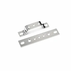
Buyers can select a Custom CNC Copper Bus Bar with Thread by reviewing the whole interface
Procurement teams should begin with the latest controlled drawing and mating-part information, not a generic request for close machining. The following actions keep commercial and engineering conversations connected.
- Mark the contact, seating, clearance, and threaded interfaces that affect the final assembly.
- Define datum features and identify the few feature relationships that genuinely need closer control.
- State the material specification, temper or condition when applicable, finish, and handling requirements without assigning unsupported electrical or mechanical claims.
- Request an inspection-plan proposal that names critical characteristics and its proposed evidence before purchase-order release.
- Set a revision and deviation workflow so drawings, samples, and production records do not drift apart.
This is also the point to review manufacturability with a supplier. A custom CNC machining review can expose datum access, tool approach, burr-control expectations, and inspection access before the part reaches a crowded assembly line.
DONGYAO, Zhejiang Dongya Electronic Co., Ltd., supports drawing-based and OEM conductive-part discussions for industrial electrical applications. The practical value is a documented conversation about configurable geometry and release information, not a blanket claim that every design needs the same process or inspection method.
When a buyer asks for a Tight Tolerance CNC Copper Bus Bar, the most useful response is therefore a clarified acceptance plan. It should say which relationships are critical, how the part will be referenced, and how changes will be evaluated before a production lot is released.
Frequently Asked Questions
What should a drawing state for a threaded copper bus bar?
It should state the thread designation and the functional geometry that positions the thread relative to mounting and mating features. It should also identify relevant datums, material and finish condition, edge requirements, and revision level; the approved drawing decides the inspection scope.
Is ASTM B193 proof that a threaded bus bar meets its drawing?
No. ASTM B193 is a material electrical-resistivity test method, not proof of thread form, location, engagement, or completed-part conformance. The drawing and its agreed inspection plan must define those acceptance requirements.
When is a Tight Tolerance CNC Copper Bus Bar appropriate?
It is appropriate when a documented assembly relationship, clearance, contact surface, or feature position requires closer control than the rest of the part. The request should identify that relationship and its datum scheme instead of applying restrictive language to every dimension.
Does Micron Precision CNC Copper Bus Bar mean every feature is controlled at the same scale?
No. The phrase should be tied to specific characteristics on an approved drawing and an achievable measurement plan. Buyers should ask which features are critical, how they will be referenced, and what evidence is requested at release.
Does IEC 61439-1 certify an individual copper part?
IEC 61439-1 concerns low-voltage switchgear and controlgear assemblies. Its applicability depends on the intended assembly and market; it does not by itself establish one component’s torque, current capacity, dimensional tolerance, or final compliance.
References for copper busbar material and assembly control
- NIST, Physical Reference Data: Copper
- Copper Development Association, Electrical Copper
- Copper Development Association, Standards & Specifications
- ASTM B187/B187M-20 product page
- IEC 61439-1 publication information
A dependable connection begins with a drawing that makes its interfaces inspectable, not with a broad promise of precision.For a drawing-based review of a Custom CNC Copper Bus Bar with Thread, DONGYAO can help technical teams organize the geometry, documentation, and release questions before production. Contact the team to start the discussion.
For related conductor products, view the product categories.