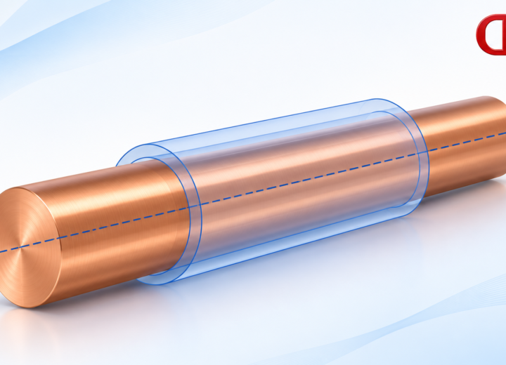
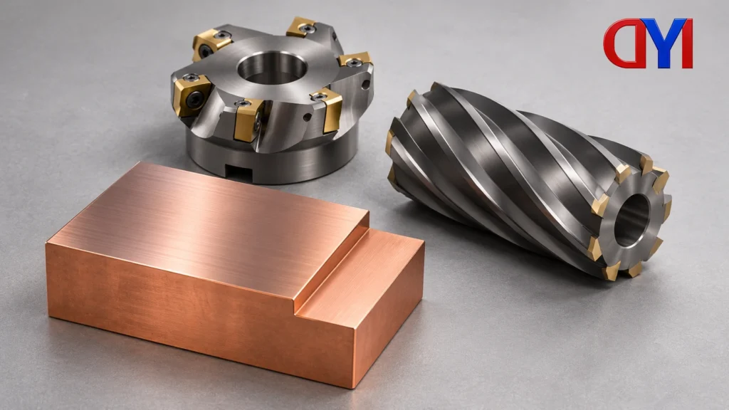
Peripheral milling removes material with cutting edges around a cutter’s outside. In the classical slab-milling example, the cutter axis runs parallel to the plane being produced. Face milling produces a face perpendicular to the cutter axis. Both belong to milling: material removal by a rotating cutter with relative feed between tool and workpiece.
Peripheral milling and face milling: read the geometry
A slab cutter illustrates peripheral milling clearly. Its outer teeth sweep across the work, generating a plane beneath a cylindrical cutter. The axis lies parallel to that plane. This is a useful starting example because the cutting region and the finished surface are easy to distinguish.
For face milling, picture a cutter approaching a broad face with its axis perpendicular to that face. Cutting can involve edges around the periphery and on the end face. The name describes the operation and its generated surface; it does not mean that only the cutter’s flat end participates.
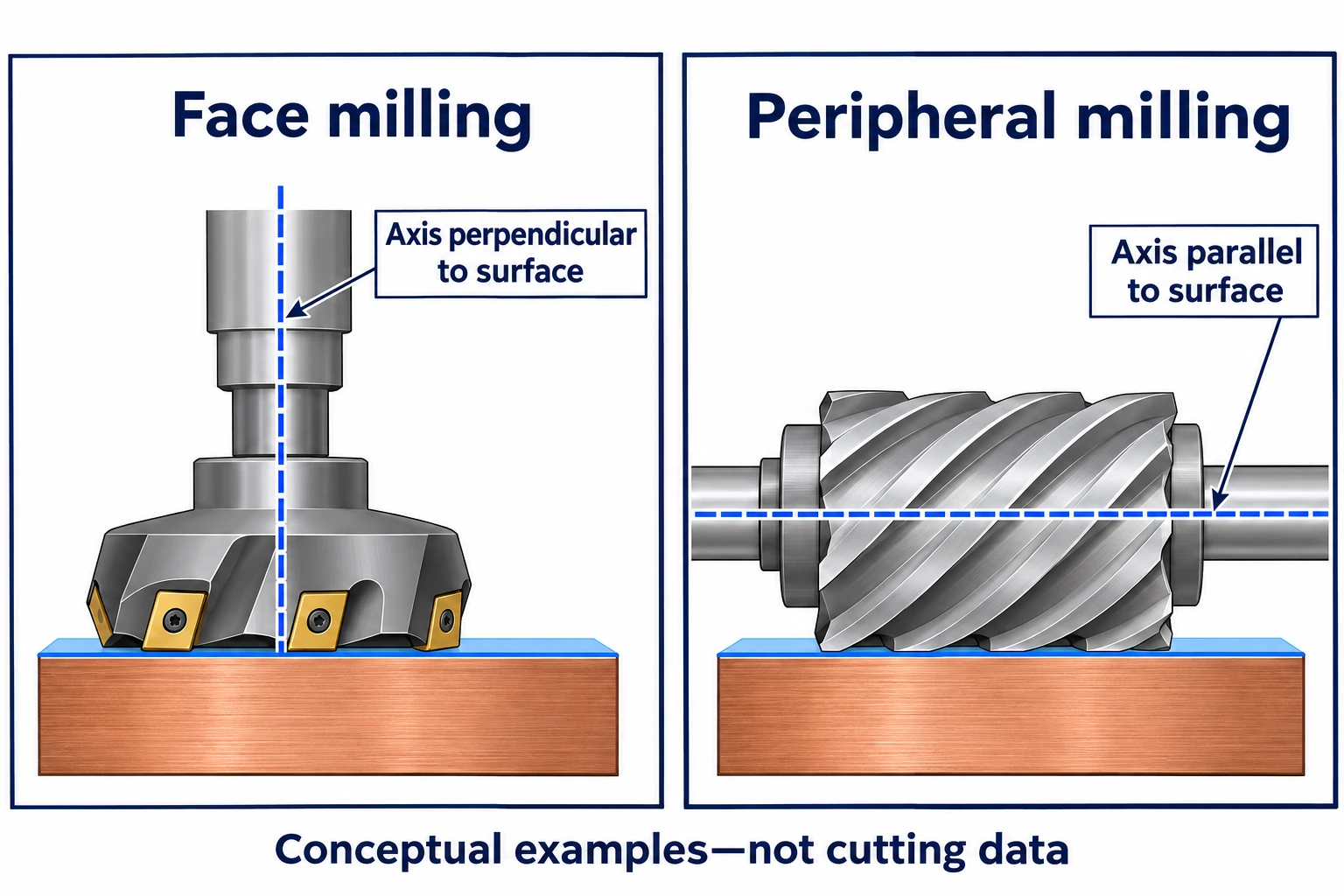
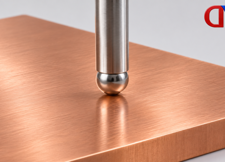
The surface matters as much as the tool silhouette. A photograph of a spindle above a part does not show which edges are cutting, what direction the tool feeds, or which surface the pass generates. Those missing details can change the description of the operation.
A cutter name does not describe every pass
Many milling tools cut with both their sides and their ends. MIT’s subtractive path-planning material distinguishes side cuts that generate walls from face cuts that generate planes. An end mill can therefore take part in different engagements within the same part program.
Calling a machine “vertical” identifies an orientation, while calling a tool an “end mill” identifies a tool type. Neither label alone tells a buyer whether a particular pass cuts a wall, a floor, or a combination. A useful explanation names the active cutting region and the surface it produces.
Face milling also accommodates different cutter concepts. Sandvik’s technical guidance treats selection as dependent on the operation. A drawing that needs a broad face does not, by itself, select a cutter or establish the resulting finish. Cutter choice belongs with the specific material, geometry and production requirements.
These distinctions also separate the method from its purpose in a sequence. Roughing removes bulk material; finishing creates final surfaces. Those terms describe the role of a pass. They do not replace the face-versus-side description of how the tool engages.
Keep four kinds of milling label separate
| Label | What it describes | What remains to be explained |
|---|---|---|
| End mill | A tool type with relevant end and side cutting regions. | Which region engages in the pass being discussed. |
| Vertical machine | A machine orientation. | The generated surface and active cutting region. |
| Face or side cut | The engagement in relation to a generated surface. | The required geometry and result of that operation. |
| Roughing or finishing | The role of a pass in the sequence. | How the cutter engages and what final requirements apply. |
These labels can appear together without conflict. A description becomes misleading when one is used as the answer to a different question—for example, using the machine orientation as proof of which cutter region produced a wall.
Apply the distinction to a pocket floor and wall
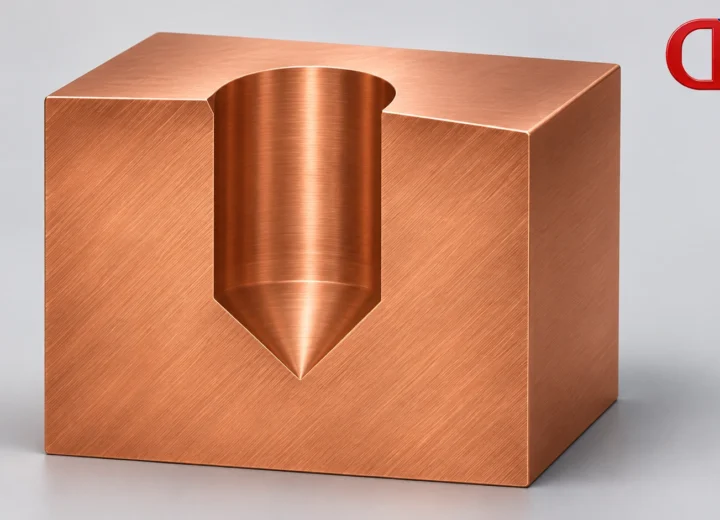
Consider a drawing with a recessed pocket. Its floor is one surface, and its upright wall is another. An inquiry that simply asks for “milling” leaves both surfaces undifferentiated. The following drawing discussion is an editorial example, rather than a proposed toolpath.
The buyer can identify the floor and wall separately, then point to each surface’s dimensional and finish requirements. The supplier can explain the proposed engagement for each region. A shared tool name is less useful than an explanation of which cutting edges produce the floor and which produce the wall.
The same discussion should distinguish the required result from the proposed method. A floor dimension belongs on the drawing; a cutter description explains a route toward it. Approval of a method name does not establish that the finished part meets its drawing.
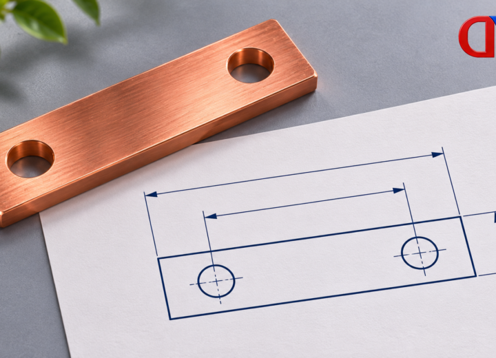
For a custom copper-bar component, the practical starting point is the part drawing and its identified surfaces. The product listing establishes the component category. It does not establish a particular milling machine, tool selection or machining tolerance.
A useful inquiry therefore ends with identifiable faces and walls, clear drawing requirements, and a request to explain the proposed route. That gives both parties something more precise to discuss than “face milling” or “peripheral milling” alone.
Read a process description from surface to engagement
Take the pocket example and read the supplier’s explanation one surface at a time. First locate the floor in the drawing. Then identify the cutter axis and the edges intended to generate that floor. Repeat the exercise for the wall. Only after those relationships are clear should a method name be used as a shorthand.
If the explanation says only “end milling,” ask which surface it describes. The tool name may be correct while the explanation remains incomplete. If it says “finishing,” ask which final surface and requirement the pass addresses. That word explains the pass’s purpose without identifying every aspect of engagement.
The broader machining-process comparison puts milling beside turning, drilling and boring. An edge at the boundary between two surfaces creates another geometry question, explained in the fillet versus chamfer guide. Neither a milling label nor an edge label should replace the actual drawing feature.
This reading order helps compare descriptions; it is not an instruction to run a cutter in a particular way. The manufacturer still needs the full part, material and production context to propose an executable route.
References
- ISCAR — Milling Applications and Cutter Basics, milling definitions and classifications.
- MIT CBA — Subtractive Path Planning, tool shapes and cut types.
- Sandvik Coromant — Face milling, operation and cutter selection.
For related conductor products, view the product categories.