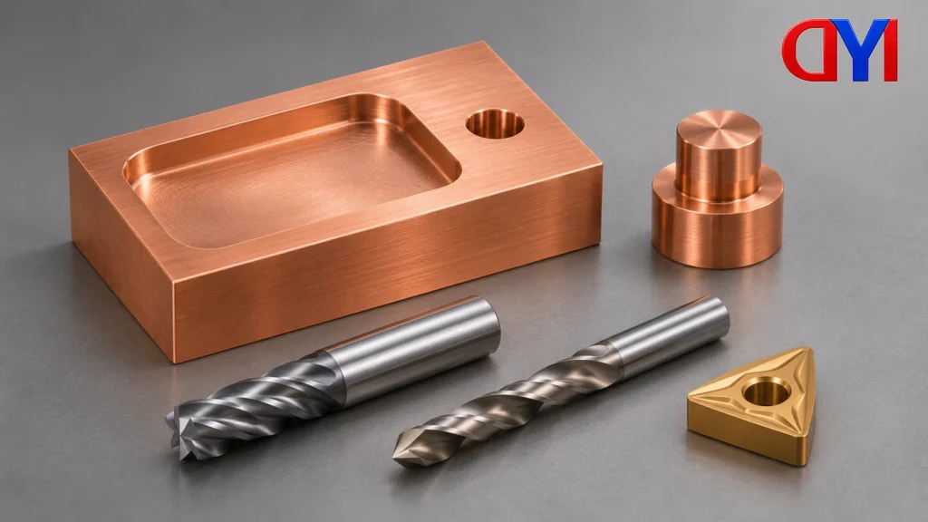
Machining for manufacturing removes material from a workpiece to create required features. Turning, milling, drilling and boring do different jobs, and one finished part may need several of them. The starting point is the drawing: identify the geometry, material and quality requirements before deciding on a process.
CNC means computer numerical control. It describes programmed control of machine-tool movements, rather than a separate kind of material. A request for “CNC machining” therefore still needs to explain what the finished part must be.
Machining for manufacturing: separate the method from the control
Industrial machining uses machine tools to remove material. These can include dedicated lathes and mills as well as computer-controlled machining centers. The cutting method describes how a feature is generated; the control system describes how the machine’s movements are directed.
A CNC program does not eliminate the need to define the stock, hold the workpiece, select tools and check the result. Design information, programming and setup must connect to the same part requirements. Computer control alone does not specify a tolerance, surface finish or inspection method.
Match the method to the feature
| Method | Typical starting feature | Question to resolve |
|---|---|---|
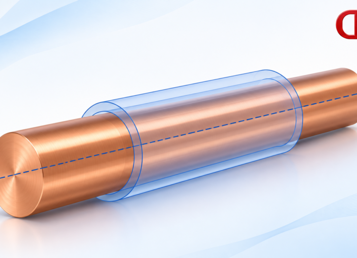
| Turning | Cylindrical, stepped or other rotational features | Which surfaces relate to the rotation axis? |
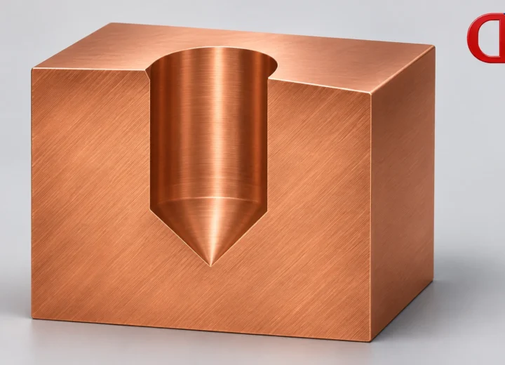
| Milling | Flat faces, pockets, profiles and shaped surfaces | Can the cutter reach the required surfaces? |
| Drilling | A hole produced in solid material | What hole size, location and final condition are required? |
| Boring | An existing hole that needs enlargement or truing | What must change from the existing hole to the finished feature? |
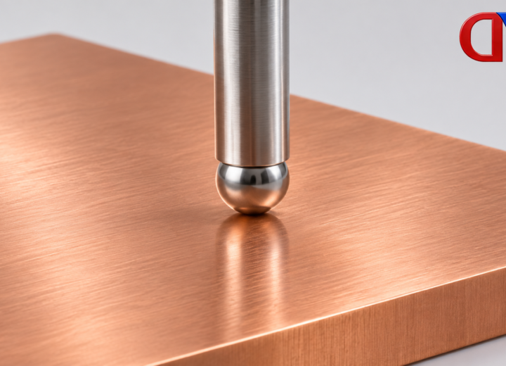
Turning commonly uses a single cutting edge against a rotating workpiece. Milling uses a rotating cutter. Drilling also uses a rotating cutting tool, but the intended feature is a hole. Boring addresses an existing opening rather than treating every hole-making task as drilling.
These are useful starting distinctions, not exclusive rules for every machine configuration. A machining center can perform more than one operation, and the final route depends on the complete part. A hole’s finished requirement may call for additional operations beyond its initial creation.
A hole request must describe the finished feature
“Drill the holes” names an operation but leaves the result partly undefined. The manufacturer still needs the final diameter, location and relevant surface requirements. If the feature is threaded or includes a head seat, a plain hole size does not describe the whole geometry.
Keep those details in the feature definition before choosing the route. The tapped-hole and threaded-hole distinction separates the thread result from a method used to make it. For a fastener-head recess, the counterbore versus countersink guide explains the different geometry questions. Naming an initial operation cannot replace either finished-feature definition.
Conversely, a drawing need not turn every required result into an unverified process instruction. Where a specific method is mandatory, identify that restriction explicitly. Otherwise, let the proposed manufacturing plan explain how the defined feature will be produced and checked.
Use geometry, access and requirements together
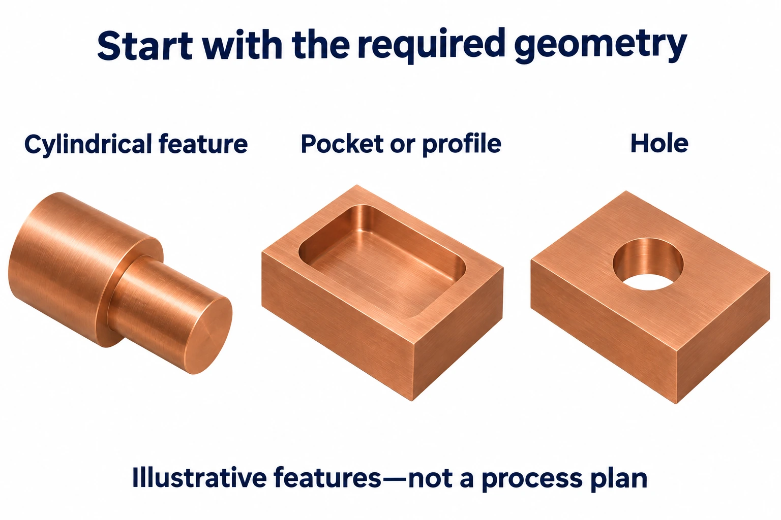
Start by marking the features that determine the part’s function. A shoulder, a pocket and a hole create different tool-access and inspection questions. Do not choose an operation solely because the part resembles a photograph of another machined component.
Then identify the material and condition. “Copper,” “brass” or “aluminum” alone leaves information unresolved. Ask the manufacturer to assess the actual grade and condition against the required features, finish and quantity. General machining explanations cannot establish a specific shop’s achievable outcome.
Also distinguish a feature requirement from a manufacturing preference. If a particular surface or relationship is critical, put that requirement on the drawing. Naming a favored machine without defining the result gives the manufacturer less useful information.
Example: turn a copper-bar drawing into process questions
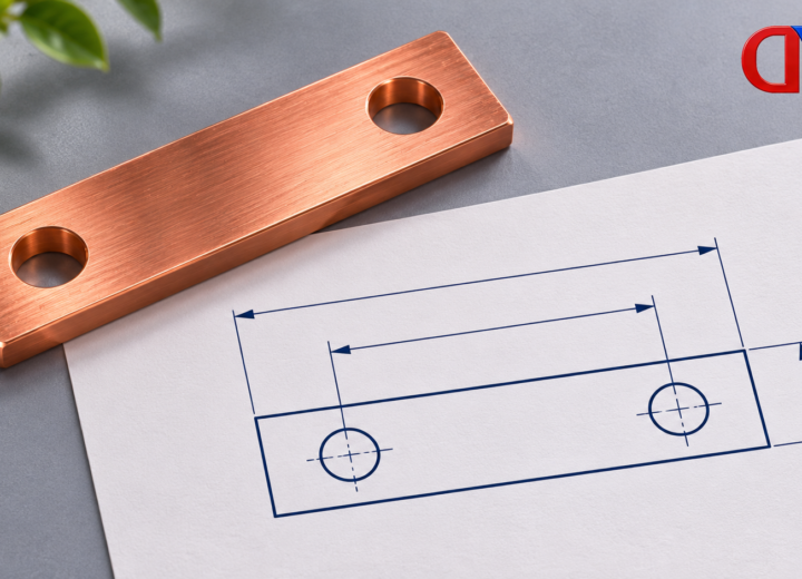
Suppose an illustrative copper bar needs a flat mating surface, a shaped recess and several holes. Instead of requesting one vaguely defined “CNC process,” identify each feature and its relationship to the others. Ask how the part will be located, which surfaces must be accessible and what evidence will confirm the finished requirements.
For the holes, provide the final drawing callouts rather than assuming that drilling alone defines the finished condition. For the recess, show its geometry and any functional constraints. For all critical features, identify the drawing revision and requested inspection records.
DONGYAO’s custom grounding copper-bar product is a relevant starting point for that inquiry. Confirm the proposed manufacturing route and available inspection evidence for the actual drawing. The general methods described here do not establish that every operation is offered or performed in-house.
Compare proposed routes against one drawing
Imagine two quotations for the same copper part. Both identify the required faces, recess and hole pattern, but their proposed sequences differ. This is not enough to conclude that one supplier misunderstood the part. Workholding, available equipment, material condition and quantity can affect the route. The useful comparison begins with whether both proposals address the same drawing revision and finished requirements.
Separate three items in the discussion. The drawing defines the required result. The proposed sequence explains a way to reach it. Inspection evidence shows how the result will be evaluated. A supplier’s description of a CNC machine belongs to the second item; it does not settle the first or third.
If one proposal omits a critical feature, seek clarification about that feature rather than asking for an unrelated machine name. If a proposed route changes a drawing requirement, the change needs the drawing owner’s approval. The manufacturing discussion can then compare actual scope without inventing a tolerance or assuming that every CNC route produces the same outcome.
References
- Sandvik Coromant: General turning
- Sandvik Coromant: Boring existing holes
- KEYENCE: Machining equipment and process definitions
- Dassault Systèmes: CNC machining definition and workflow
For related conductor products, view the product categories.