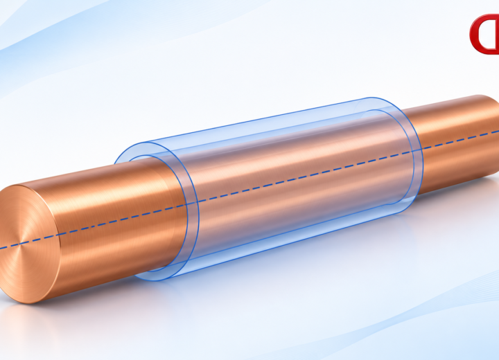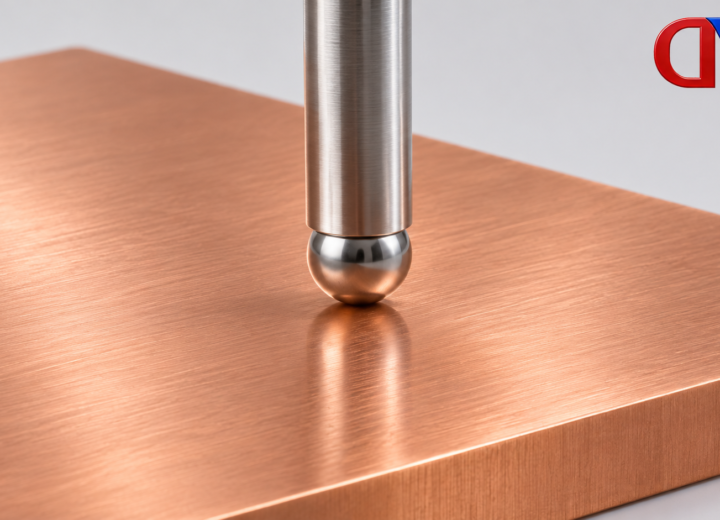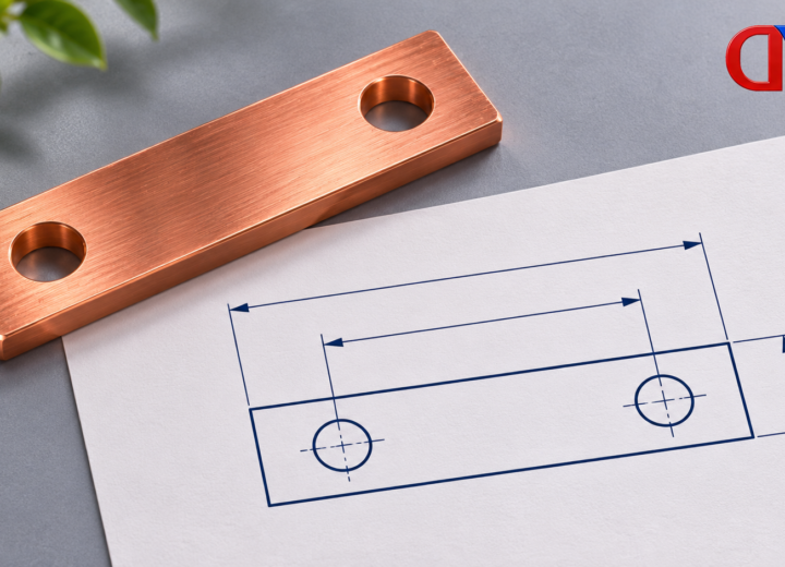
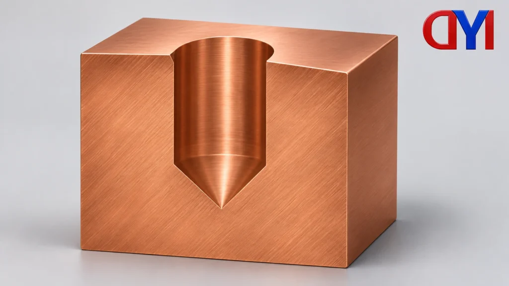
A blind hole ends inside a workpiece instead of passing through the opposite face along its axis. A through hole crosses the material. For a blind feature, the drawing must make the intended depth and bottom form clear; the word “blind” alone does not define either one completely.
Blind hole meaning and bottom shape
Termination describes where a hole ends. Bottom shape describes the geometry at that end. Autodesk’s Inventor documentation treats termination and drill-point form as separate inputs, including flat and angled points. A blind hole therefore should not automatically be read as a flat-bottom pocket.
The same distinction applies when a drawing is translated into a model. A distance-based termination needs an identified starting surface and endpoint. A through-all instruction has a different purpose: it extends the hole through the intersected material rather than leaving the specified blind end.
The following discussion concerns machined mechanical holes. It does not describe the layer connections of a printed-circuit-board blind via or establish a pressure-sealing function.
Separate four questions in the hole definition
| Question | What it identifies | What it does not settle |
|---|---|---|
| Blind or through? | The termination relative to the workpiece. | The bottom form of a blind hole. |
| Flat or angled bottom? | The geometry at the closed end. | The reference used for a depth value. |
| Cylinder or tip depth? | The endpoint measured from the stated start. | The required threaded portion. |
| What thread extent? | The defined threaded region, if present. | The full drilled-cavity extent or a manufacturing allowance. |
Keeping these questions separate helps when two records use the same feature name. A shared “blind hole” label can conceal different endpoint or bottom-form assumptions. Compare the defined geometry before translating the record into a machining instruction.
Which endpoint does the depth control?
An angled-bottom hole has a cylindrical region followed by a pointed region. Depth to the end of the cylinder is shorter than depth to the deepest tip when both begin at the same entry surface. The two values describe different geometric extents of the same hole.
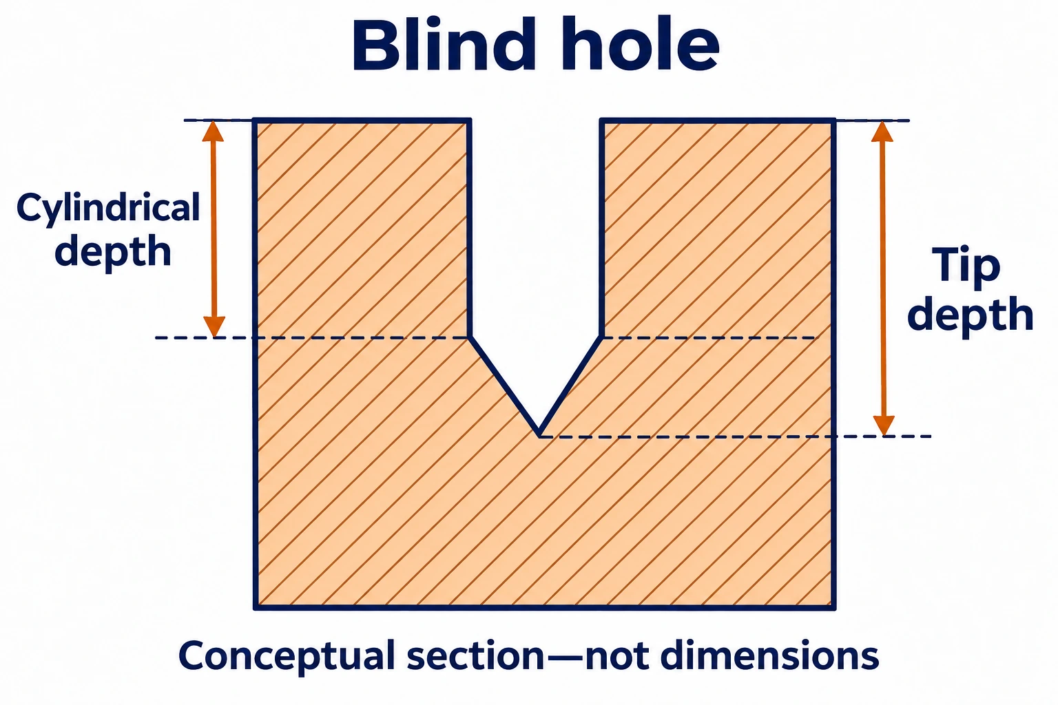
PTC’s Creo drilling reference provides “By Shoulder” and “By Tip” options to distinguish those tool-depth references. Its Elements/Direct blind-hole-step documentation separately defines drilling depth as the cylinder length excluding the drill tip. These software examples show why the reference matters; they do not establish one universal interpretation for every drawing or CAD system.
A note saying only “depth” should consequently be read with its leader, section view and governing drawing conventions. If the intended endpoint remains unclear, the designer should resolve it. The supplier should not choose a cylindrical or tip-depth interpretation simply because one matches a software default.
If the hole includes a thread, there is another extent to identify. PTC’s hole-note documentation separates drilled depth from thread depth. The threaded portion should not be assumed to reach the deepest point of the drilled cavity. Define the required thread extent separately, without treating the drill point as usable thread length.
Example: two depths from the same starting face
Take a fictional section with a cylindrical depth of 10 mm and a deepest-tip depth of 12 mm, both measured from the same entry face. The 10 mm label describes the cylinder extent; the 12 mm label reaches the tip. Their 2 mm difference belongs only to this assumed geometry. It is not a general drill-point allowance or a recommended dimension.
If one quotation repeats “10 mm deep” without stating the endpoint, it has not yet shown whether it agrees with that section. Ask which endpoint the quoted value uses, then compare the relevant extent. Switching from cylinder to tip interpretation changes the defined result even though the printed depth number may remain unchanged.
If the feature also has an internal thread, identify its required extent independently. The tapped and threaded hole guide explains the thread-result and production-method distinction. Neither the 10 mm nor 12 mm example value automatically defines the usable threaded length.
An entry recess raises a separate question at the other end of the hole. The counterbore and countersink comparison addresses that seat geometry. Keep its dimensions distinct from the closed-end depth reference so a drawing revision can show exactly which feature changed.
Resolve the callout before the machining inquiry
Consider a component drawing with a hole diameter and a depth value, but no clear depth endpoint. This editorial example begins by locating the entry surface and the hole’s section view. The buyer and designer can then confirm whether the value controls the cylindrical region or the deepest point.
The next question is whether the bottom form has a functional requirement. If a flat bottom is required, the drawing should say so rather than relying on the blind-hole label. If an angled bottom is acceptable, its interpretation still needs to agree with the stated depth.
Any remaining-material requirement also belongs in that review. Showing the hole against the component section makes the relationship visible, but this guide provides no minimum wall or remaining-thickness rule. Such a requirement must come from the actual design rather than from the illustration’s proportions.
For a threaded feature, attach the thread requirement to its own extent. The drawing handoff can then distinguish the entry surface, diameter, depth endpoint, bottom form and threaded portion. That resolves the geometry without prescribing a tap allowance or a manufacturing sequence.
For a custom copper-bar component, include those clarified details with the inquiry. The product category does not verify a drilling depth range or blind-thread capability. A defined feature gives the supplier and buyer a specific result to discuss and a basis for agreeing how it will be checked.
References
- Autodesk Inventor — Hole dialog box, bottom form and termination.
- PTC Creo — To Define Depth, shoulder and tip references.
- PTC Elements/Direct — Blind Hole Step Parameters, cylinder-length definition.
- PTC Creo — Hole Notes, drilled and threaded extents.
For related conductor products, view the product categories.